ㆍ 목적에 대응하는 조명 방법,관찰 방법,배율의 선택이 가능하고,다양한 측정방법에도 사용가능합니다.
ㆍ높이 측정에서의 고르지 않은 상태를 최소한으로 하는 포커스 센서를 준비.높이·깊이 측정을 효율 좋게 측정 할 수 있습니다.
ㆍ interface unit을 사용하여 퍼스널 컴퓨터에서의 측정 데이터의 보존,관리가 가능합니다
ㆍ 텔레비전 카메라,사진 촬영 장치를 option로 준비
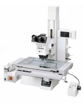
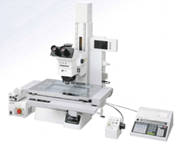
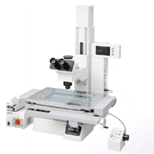
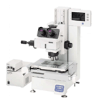
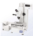
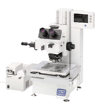
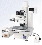
STM6-LM/STM6
신뢰성 있는 Line-UP. 다양한 ACC’S로 모든 측정 요구에 대응가능
최첨단 System 성능을 갖춘 MEASURE SHOP. 신기술을 적용한 고정밀도 현미경으로서 고정밀도, 내구성은 기본이며 성능,측정요구까지도 다종다양하게 대응할 수 있는 제품력을 갖추었습니다. 대형시료에서의 빠른 검사를 실현한 STM6-LM. Class 최소의 Body로 고정밀도의 능력을 발휘하는 STM6. 풍부한 ACC’S를 통해 유저에게 최적 시스템을 제공 할 수 있습니다. 전동 Focus의 세계 최초 도입, 이상적인 UIS2 광학계, Counter 일체의 고강도 Body의 채택 등 실제적인 다양함으로 모든 측정요구에 충족하는 MEASURE SHOP. 첨단의 기능과 장비를 탑재한 측정현미경의 등장입니다.
ㆍ 높은 정밀도와 내구성을 실현하기 위한 흔들림 없는 기술력과 엄격한 traceability.
ㆍ 조작의 편리함을 Concept으로 사용하기 편리한 기능과 확장성을 철저히 추구.
ㆍ 전동 Focus를 표준 탑재하고, 대형시료를 고정밀도로 빠르게 측정
ㆍ Foot-Print에 뛰어난 소형, 고기능설계. 다채로운 조합을 실현
ㆍ 미소 영역과 단차가 있는 모든 시료를 순식간에 focusing
ㆍ MM6-CAL22 :Compact한 Body에 다채로운 연산기능을 탑재
Special Features : Reliability
높은 정밀도와 내구성을 실현할 수 있는 우수한 기술력과 엄격한 Traceability ■ 빈틈 없는 설계력,고도의 기술력이 품질향상과 Process개선에 공헌
ㆍ경년변화에 강한 고강성 Body & Stage 오랜 기간동안 이루어진 측정현미경에의 대한 전념과 고객과의 대화를 통해 배양된 Know-how, 기술력의 모든 것을 투입한 MEASURE SHOP. 정밀도, 강성을 기본으로 측정기로서 가장 중요한 정밀도를 오랜기간 유지하기위해 경년변화에 강한 고강선 Body와 Stage를 개발하였습니다. Guide-way에는 우수한 진직도(Straitness)를 얻을 수 있는 Linear guide방식을 채용했고 독자적인 Scale을 내장하여 높은 신뢰성에 중점을 두었습니다.
ㆍLinear Scale이 Sub-micron을 실현합니다. Scale의 정밀도는 측정현미경의 정밀도를 좌우하는 중요 포인트로 OLYMPUS에서는 독자적으로 개발한 고정도 광학식 LinearScale에서 얻어진 광정보를 전기적으로 처리하여 측정합니다. Scale 내장위치도 Abbe의 정리(측정해야 하는 길이와 Scale이 그 측정방향에 일직선으로 배열된 위치가 가장 오차가 없다)에 근거하여 오차를 최소로 하였습니다.
■ 국제규격의 Traceability체계가 고품질을 보증 또한 치밀한 After Service로 제공
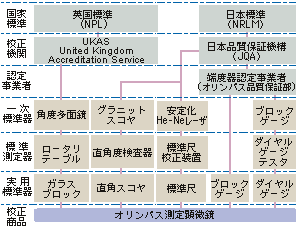
ㆍ고품질을 보증하는 엄격한 제조공정. 고정밀도 추구를 위하여 제조에서 조립에 이르기까지 일본 내 제1급환경level에서 정비. 최상급의 항온공장에서 엄선한 소재를 가공하고 숙련자의 손을 통해 한대 한대 소중한 제품으로서 마무리를 합니다. 또 OLYMPUS의 측정현미경은 부품 하나에서 완성품에 이르기까지 엄격한 Traceability를 기본으로 관리되어지고 있습니다.
Special Features : LED 조명
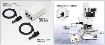
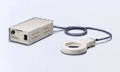
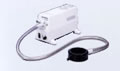
▶ 반사, 투과 조명용의 밝고 깨끗한 LED조명장치 [MM6-IL]시리즈
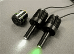
ㆍ보다 밝고 깨끗한 상으로 관찰효율이 UP 투과, 반사용 LED조명 유닛은 할로겐의 황색보다 자연광에 가까운 백색 LED를 채용했습니다. 관찰상이 밝고 깨끗하여, 시료의 색을 충실히 재현하며, 밝기를 바꿔도 색이 변하지 않고 LED조명은 형광등처럼 변동이 없기 때문에 장시간 작업으로 인한 눈의 피로를 경감시켜줍니다.
ㆍ긴 수명, 낮은 소비전력으로 소비량을 삭감
ㆍ정숙, 저 발열에 의한 측정신뢰성의 향상
ㆍ보다 작은 스페이스의 실현
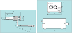
ㆍMM6-IL dimensions
언제라도 최상의 상태를 유지하도록 정기정검제도 service를 실시
OLYMPUS는 계약에 맞추어 일정기간 내의 정기점검을 실시합니다. 연1회 정기점검과 연2회 정기점검이 가능하고 계약기간 및 점검회수는 상담에 따름니다. 또 고객의 상황에 맞추어 수시점검도 시행하고 있습니다.
<점검범위> 점검보고서에 따라서 기능점검과 정밀도 점검을 실시하여 장치의 상태를 평가하는 것을 기본으로 하고 있습니다. 부품교환이 불필요한 수리에 대하여는 그 장소에서 바로 점검이 가능합니다. 또 점검의 결과 별도 수리가 필요한 경우에는 상담을 바랍니다.
<점검내용> ● 정밀도 점검, 교정의 실시 ● 기능 Check ● 윤활유 교환, 가벼운 수리 및 간단한 조정 ● 광학계의 점검과 청소 ● 외관청소 ● 점검보고서, 검사성적표의 발행
사람에게 편안함을 주제로 간편한 사용기능과 확장성을 철저 추구 ■ 장시간의 측정에서도 피곤하지 않도록 사용자를 위한 이상적 설계
ㆍZ축 측정을 빠르게 행할 수 있는 전동 Focus (STM6-LM,STM6 전동type)핀트 조정과 높이 및 깊이의 측정시 조작성을 대폭 향상시킨 전동Focus를 Olympus가 처음으로 채택. 조동과 4단계의 미동(800,400,200,50㎛)변환을 간단하게 Z축 조작 Box에서 조작 가능하게 하여 작업시의 피로가 대폭 경감됩니다.
ㆍ보기쉬운 이상적인 위치에 부착된 Counter 현미경 본체와 일체화된 표시부가 관찰위치와 거의 동일선상에 위치하여 작은 시선의 이동만으로 측정치의 확인을 할 수 있어 관찰,위치 맞춤에만 전념 할 수 있습니다.
ㆍEdge 관찰, 외관 Check에 뛰어난 UIS광학계를 채용 UIS광학계가 실현하는 우수한 고해상력과 Contrast에 의한 Edge의 상을 통해 측정, 외관검사의 비약적인 향상을 도모합니다.
ㆍ인간의 눈의 분해능을 고려한 Raticle에서 간단한 위치 맞춤. 측정현미경에서는 측정물과 Raticle을 정확히 맞추는 것이 중요합니다. 직선을 맞추는 것은 하나의 선으로 행하는 것보다 Raticle및 파선이 있는 쪽을 정확이 행하는 것이 더 정확한 Data를 얻을 수 있습니다. 이러한 인간의 눈의 특성과 분해능을 분석하고 초점판에 Raticle과 파선을 넣어서 맞춤 정밀도를 향상시킵니다.
Special Features
STM6-LM
■ 전동 Focus를 기본장착하고, 대형시료를 고정밀도로 빠르게 측정
ㆍ전동 Focus 채용에 의하여 Z축 측정시의 피로를 대폭 경감
전동 Focus를 기본장착하였고 손쉬은 조작Box로 핀트조정을 행하기 때문에 지금까지의 무리한 자세에서의 Z축Handle 조작은 필요없습니다.
ㆍ효율적인 공간 활용, 일체형Body(전계장비)。 본체에 전기장치 System을 내장한 Counter일체형 Body에 Data통신 Interface부분에 RS232C를 내장하여 컴퓨터와의 자료 전송과 Printer 등의 외부기기와의 접속이 더욱 용이하게 되었습니다. 더욱이 컴퓨터에 부착된 Data는 MicroSoft Excel등으로 Database화가 가능합니다.
ㆍ광범위를 일시에 빠르게 검사할수 있는 클러치 타입의 대형스테이지
250㎜×150㎜ 의 큰 측정범위를 갖는 Stage를 탑재. X.Y 구동 각각에 Clutch free기구를 장비, 레버 하나로 조동미동을 빠르게 변환이 가능합니다. X line위와 Y line위, XY 평면상의 자유자재로운 Stage운송이 가능하게 되어 대형시료에서의 빠른 검사를 실현하였습니다. 또 Stage위에 동시에 다수의 시료를 놓고 측정하는 것도 가능합니다.
STM6
■ Foot Pinter에 우수한 소형화, 고기능화적인 설계.선택가능한 Body, Stage등 다양한 조합을 실현
ㆍ설치장소에 관계없는 적은 공간을 차지하는 Body (W)295㎜×(D)429.4㎜의 Compact한 Body에 다채로운 기능을 집약함으로 이 class에서 최소설계를 실현하였습니다.
ㆍ용도에 맞춘 4 Type, 충실한 Line-Up 0.1㎛ 검출의 전동 3축 type, 매뉴얼3축type에는 0.1㎛ 검출과 0.5㎛ 검출용을 준비. 또한 매뉴얼 2축 type의 0.5㎛의 검출용이 있습니다.
Special Features : Auto Focus
미세한 영역과 단차가 있는 시료를 고정밀도로 빠른 시간에 Focusing ■ 개인차에 의한 오차를 없앤 고정밀도 측정과 빠른 검사를 실현
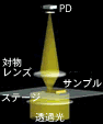
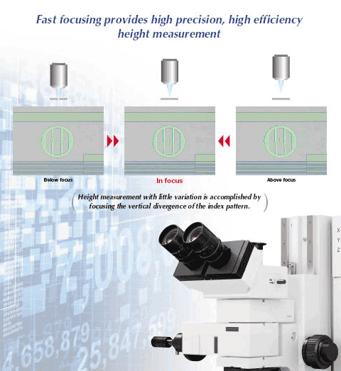
ㆍ간단히 Add-on 가능한 Auto Focusing Unit STM6 series에서는 one-shot와 trace기능을 추가하여 Assist의 3Mode를 탑재. 섬세한 조작이 요구되어지는 목시에 의한 높이 깊이의 측정을 모드의 구분 사용에 의하여 자동화가 가능합니다. 개인차에 의한 오차의 발생이 없는 동시에 X,Y Handle에서 손을 이동하지 않고 관찰할 수 있는 등 Z축측정의 효율을 대폭 향상시켰습니다. 그리고 중간경통 type이므로 용이하게 Add-on이 가능합니다. [원리도]
1.one shot 거친 핀트 상태에서 Auto-Focus 실행으로 시야중심에 신속하게 핀트를 맞춘다.
2.Trace 초점이 맞는 위치를 추적하면서 항상 핀트가 일치한 상태를 유지한다. X,Y축 측정시의 핀트 맞춤이 불필요하기 때문에 작업효율이 한단계 향상됩니다.
3.Assist 측정하는 시료면이 Trace범위를 벗어난 경우, Auto Focus가 대기 상태가 됩니다. 전동 focus에서 대물렌즈를 상하로 움직여 다시 Trace범위에 넣은 시점에서 Auto focus가 작동하고 초점위치가 정지합니다.
ㆍ고배율 대물렌즈에서 1㎛의 높은 재현성 반사 Active?공초점 방식을 채택함으로 시료의 경사?표면의 거친 정도에 대하여도 안정된 초점을 실현. LMPlan100× 대물렌즈에서 1㎛의 재현성을 가능하게 하였습니다.
대물렌즈
재현성(2σn-1)
LMPlan20×
2㎛
LMPlan50×
1㎛
LMPlan100×
1㎛
*당사기준 샘플에 의한 수치입니다.
ㆍ미소영역에서도 Auto-Focus가 가능 Laser의 Spot지름이 50x,100x 대물렌즈 사용시 φ1㎛를 실현. 미소영역의 Z축 측정이 가능하게 되었습니다. Bonding Wire등에서도 대응 가능합니다.
대물렌즈
Spot지름
LMPlan20×
φ2.5㎛
LMPlan50×
φ1㎛
LMPlan100×
φ1㎛
*계산에 의한 이론치입니다.
Options
■ 효율적인 측정을 위해 필요한 기능을 선택, 추가할 수 있는 다양한 ACC’S를 준비
ㆍ고배율에서의 검사와 미분간섭관찰하에서의 측정 다양한 측정영역에 대응하기 위하여 반사조명 장비를 STM6-LM, STM6에 각각 3종류씩 준비하였습니다. 측정대물렌즈와 Revolver을 이용하여 금속대물렌즈에 대응하고 명시야,암시야, 미분간섭관찰까지 가능. 용도에 따른 장비 추가로 System Up-grade가 가능합니다.
ㆍ측정효율을 비약적으로 높인 Add-on 가능한 장비 준비 높이,깊이 측정을 자동화 하는 Auto-Focusing Unit과 시료의 Edge를 자동검출하는 투과Edge Sensor Unit을 준비. 측정시간 단축 및 피로를 경감할 수 있고, 측정효율을 대폭 향상하였습니다.
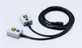
ㆍ투과Edge Sensor 시료의 Edge를 자동검출하는 Edge Sensor Unit을 용이하게 추가할 수 있습니다.시료의 Edge를 Sensor부에 통과시키는 것만으로 Edge를 검출할 수 있어 개인차에 의한 오차를 해소함으로, 목시 측정에 비교하여 재현성이 향상됩니다. 정확하고 안정된 Data를 얻을 수 있고 측정시간도 대폭 단축이 가능합니다.
ㆍMM6-RHS250,MM6C-RHS100/ RESET SWITCH
XY counter값의 Reset을 적은 동작으로 할 수 있습니다.
ㆍMM6-RK01/Remote cube Unit
XYZ counter Reset, Data 출력과 1/2 counter의 변환을 적은 동작으로 할 수 있습니다.
ㆍMMFS01/Foot Switch
Printer, 2차원 data처리장치등에서의 Data 전송을 Hand-free로 할 수 있습니다.
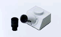
ㆍMM6-EMO/정립단안 경통
정립상의 단안경통입니다. Cross line이 있는 접안렌즈 MM6-OCC10×과의 조합으로 사용하는 것이 가능합니다.
ㆍSZ-FLR/형광등 조명 장치
Ring 형광조명등에 의해 그림자와 번짐이 없는 조명이 가능합니다.(별도 Adapter가 필요합니다)
ㆍLG-R66/Ring Light Guide
관찰에 불필요한 표본의 그림자를 차단하여,밝고 깨끗한 관찰상을 얻을 수 있습니다.(별도 Adapter가 필요합니다.)
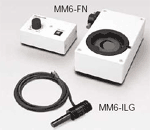
MM6-FN
제품의 특징
FN지표에 따라 간단하게 초점을 맞출 수 있으며 개인차에 따른 측정오차를 최소화하고, 단차 측정시간을 단축
Arm일체형 투광관의 채택으로 시스템구축 및 장치조합의 자유도가 더욱더 향상되었습니다. 반사투과조명에 대응한 BX51-type. 반사조명전용에 대응한 BX51M-type을 준비하였습니다. 또 BX-URA2(Universal반사투광관)과의 조합에 의한 형광관찰도 가능합니다.
IR관찰에 대응
BX51/BX51M-IR
현미경 본체와 반사투광관은 그대로 근적외선 대응의 Unit을 조합하는 것 만으로, 반사투과의 근자외선관찰이 가능합니다. 실리콘 웨이퍼 내부와 패키지 후면내부, CSP bump등의 관찰을 가능하게 하는 근적외선현미경으로서 사용이 가능합니다. BXFM system과 조합하는 것이 가능합니다. 근적외선관찰에 대응
가시영역에서 근적외 영역까지의 수차보정된 5X ~ 100X의 IR대물렌즈를 갖추고 있습니다.
근적외관찰을 용이하게 하는 직통을 장치에 통합시겼습니다.
반사투과본체와의 조합으로 투과광 근적외선 관찰에도 대응가능합니다.
Motorized 대응
BX61
Focusing, 조광, 반사투과변환 등이 전동화된 BX61을 준비하였습니다. Control Software로 일련의 현미경 조작을 Macro화하고, Key-pad나 Computer및 팜톱 단말기에서 제어가능합니다.
관찰법 및 대물렌즈의 배율과 연동한 조광과 각종 광학소자의 삽탈 등, 관찰에 동반되는 광학조정을 세밀 하게 설정하는 것이 가능합니다. 번잡한 일련의 조작을 Macro화하여, 현미경 본체에 장비된 버튼(focus, 조광 등 모두 9개소)과 핸드스위치, computer의 key-pad등에 할당하고 보턴 하나로 관찰조건을 재현할 수 있습니다.
고속, 고내구성 전동 Revoler, Motorized coaxial Revolver,전동 명시야 투광관, 전동 Universal 투광관,반사 Auto Focus Unit, Filter wheel등의 각종 전동 Module을 준비하였습니다.이러한 전동 Module은 바로 옆의 핸드스위치와 Computer에서 제어가능합니다.
모든 대물렌즈에서 완전한 동심을 얻을수 있는 (Motorized coaxial Quintple Revolver) U-P5REMC를 준비하였습니다.
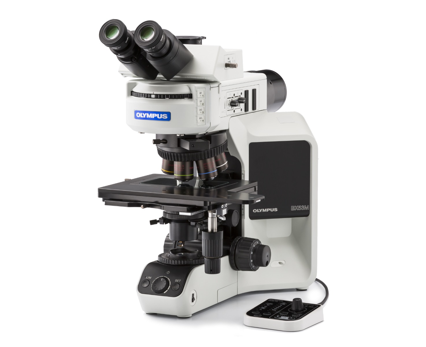
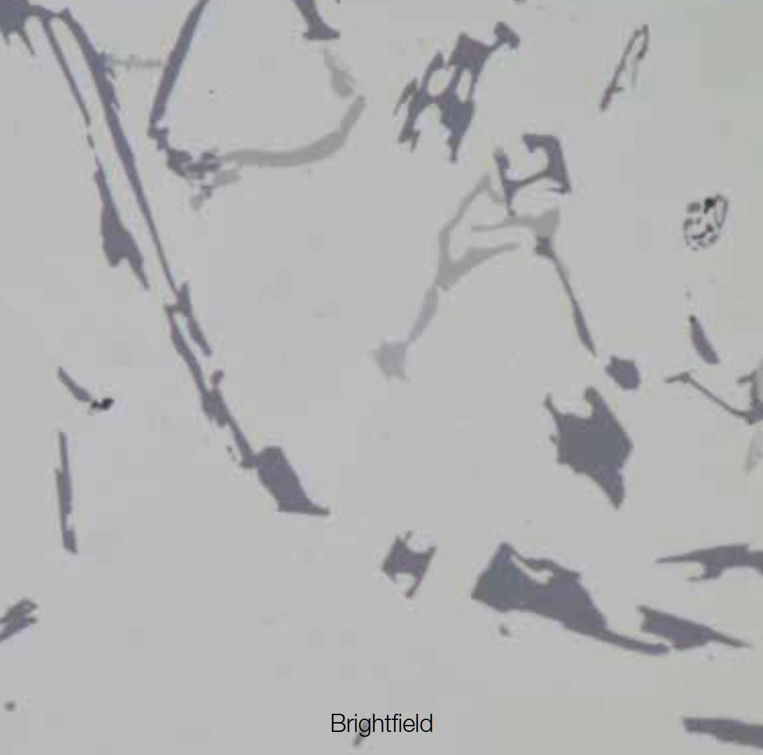
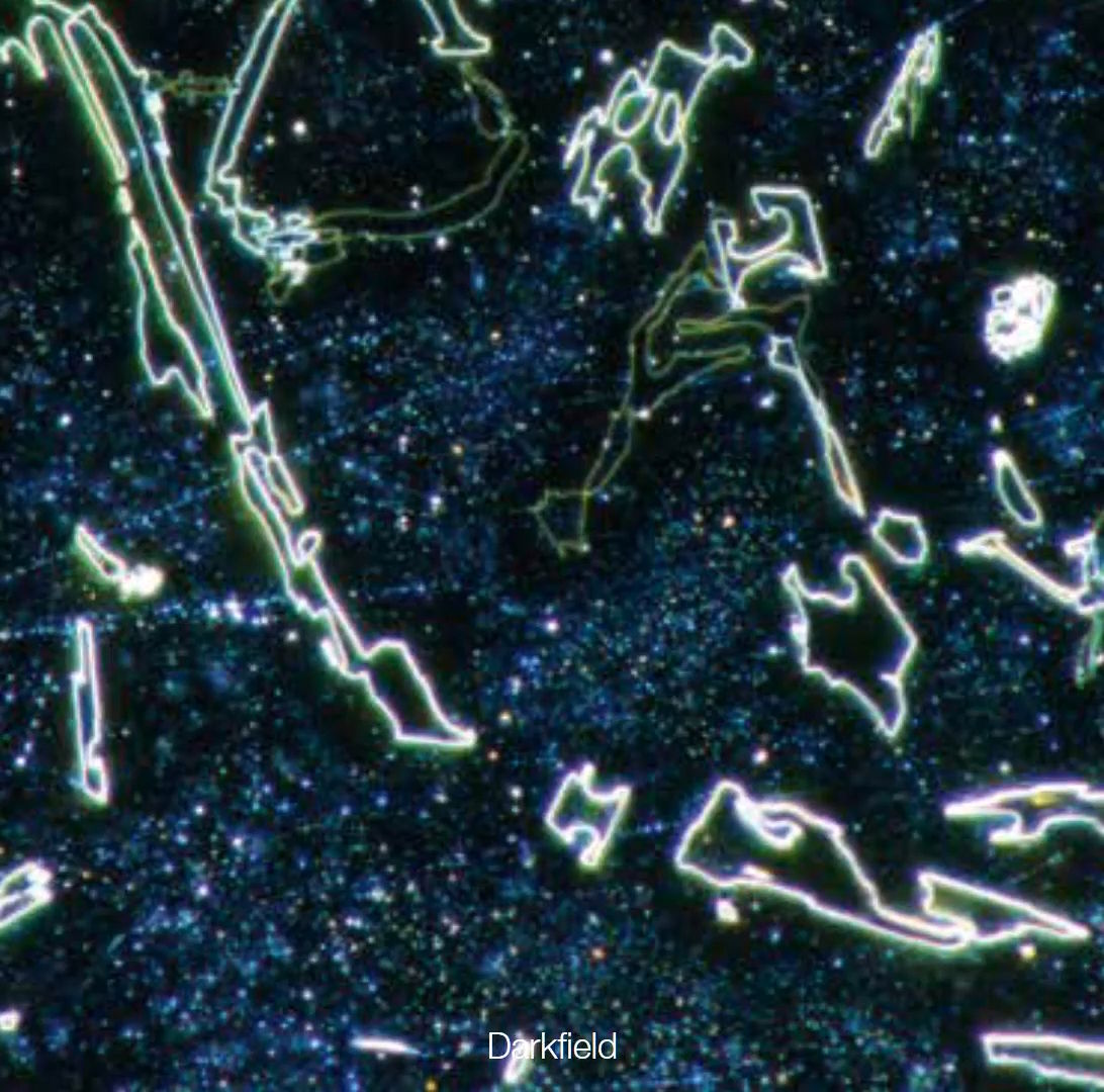
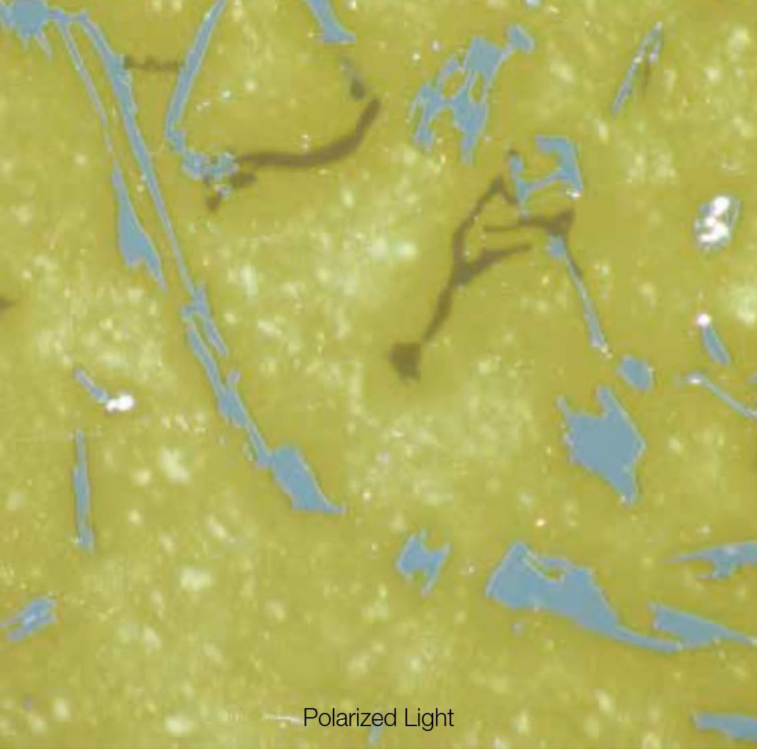
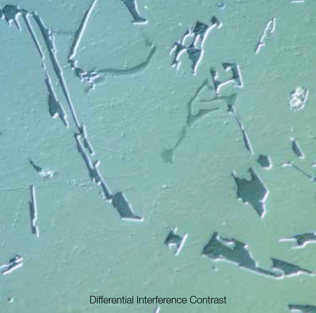
Bright Filed Image with BX53M Industrial_microscopeDark Filed Image with BX53M Industrial_microscopeSimple Polarized Image with BX53M Industrial_microscope (Simple Polarization)DIC Image with BX53M Industrial_microscope반사형 현미경 (Reflected Microsocpe) 검경법_명시야, 암시야, 간이편광, 미분간섭관찰(DIC)BF (구상흑연주철 )편광 (구상흑연주철 )Fluorescence image구상 흑연 주철의 명시야, 간이편광 이미지 와 형광이미지(우측) 입니다.
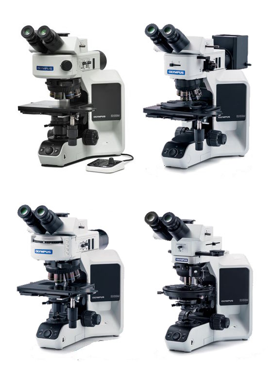
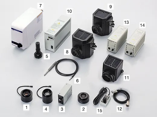
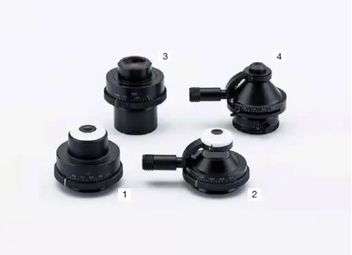
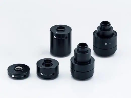
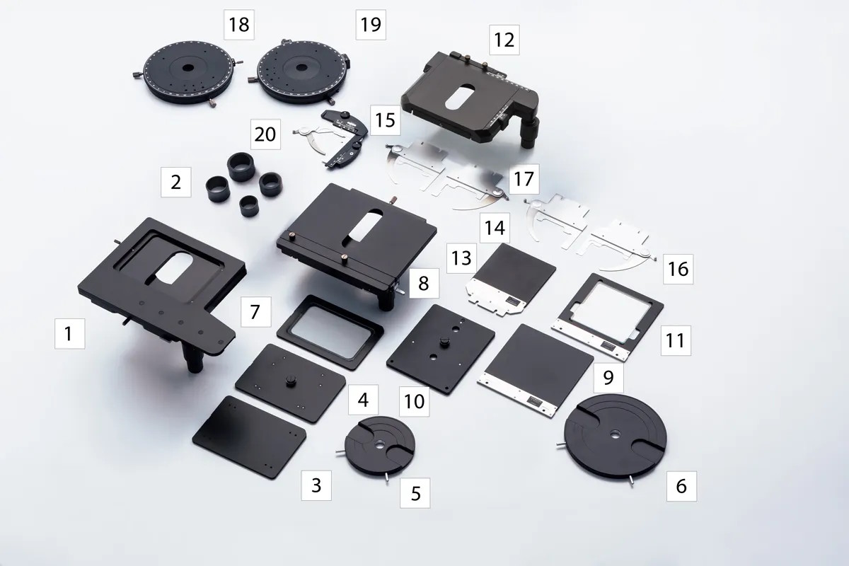
BX53M 구성을 위한 다양한 모듈( Module )
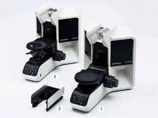
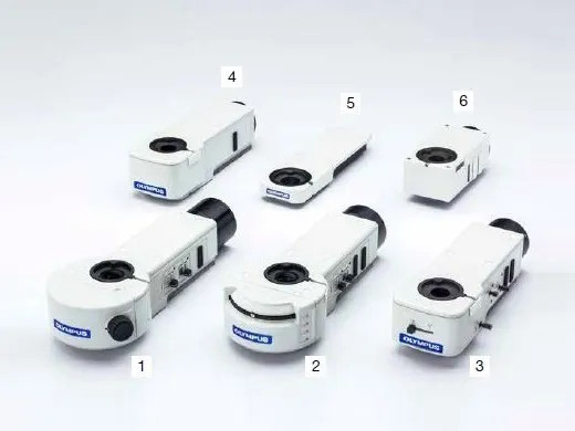
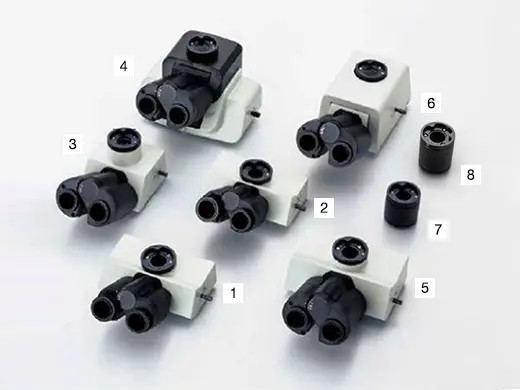
Body Frame for BX53MILLUMINATOR for BX53MHead for BX53MLight soruce for BX53MCondensor for BX53MC-mount adapter for BX53MStage for BX53M Industrial_microscope실험 목적에 적합한 모듈과 대물렌즈를 선택 하여 조립하시면 – BX53M 1Set – 가 됩니다 . 상기 이미지는 구매 희망자의 이해를 돕기 위한 것으로, 일부 모듈은 누락되어 있으니, 구매 하시기 전에 전문가의 상담을 받으시기 바랍니다.
UIS2 Objectives ( 대물렌즈 )
UIS2 Objectives for BX53M Industrial_microscope
추가 유닛 ( Option )
Flexibility for Sample Height and Weight
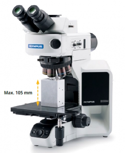
Body Frame 확장을 통한 최대 105mm(4.1인치)의 샘플을 스테이지에 올려서 검경이 가능합니다.
향상된 포커싱 메커니즘으로 최대 6kg 중량의 샘플을 올려 놓고 관찰 할 수 있습니다. (상기 중량은 스테이지의 중량이 포함된 값입니다. )
Flexibility for Sample Height and Weight Samples up to 105 mm can be mounted on the stage with the optional modular unit.
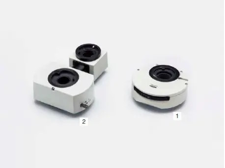
광로 변환 장치 및 추가 변배율 장치
Various types of accessories for multiple purposes. For use between tube and illuminator.
BXFM with BX3M-KMA-SBXFM with U-KMAS높이 측정 모듈 & Lagre StageBXFM은 한정된 BX53M의 고가의 Body Frame의 한계를 벗어난, 저렴한 Body 구성 뿐만 아니라, 다양한 관찰 환경에 맞추어 구성되어 판매 되고 있습니다.
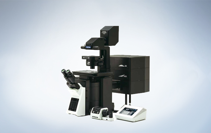
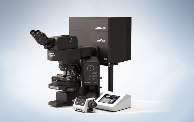
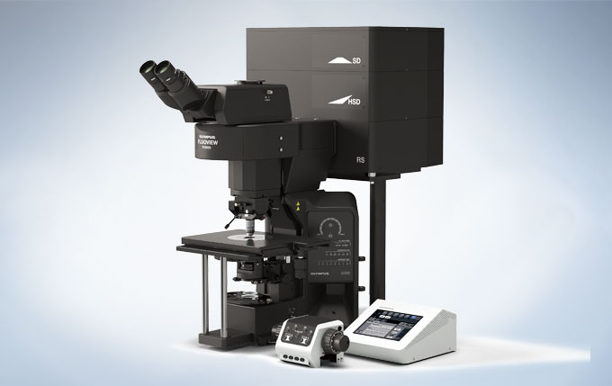
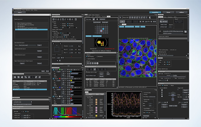
The FLUOVIEW FV3000 series is designed to meet some of the most difficult challenges in modern science. Featuring the high sensitivity and speed required for live cell and tissue imaging, the FV3000 enables 2D-6D (x,y,z,t,λ,p) macro to micro imaging of cells, tissues, and small organisms. With an intuitive and adaptable user interface, the FV3000 supports complete workflows from image acquisition to processing and analysis. Particular attention has been paid to the needs of cell biology, cancer research, and stem cell research, and with two new upright configurations, the FV3000 is also poised to meet the needs of neuroscience, electrophysiology, and developmental biology.
High Sensitivity Multi-Channel Imaging
A Fully Spectral System with Sensitivity and Accuracy
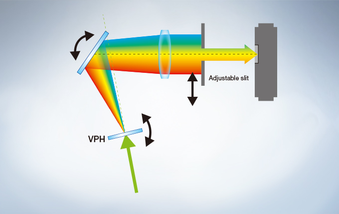
The FV3000 series employs Olympus’ TruSpectral detection technology. Based on patented* Volume Phase Hologram (VPH) transmission and an adjustable slit to control light, the spectral detection is highly efficient, enabling users to select the detection wavelength of each individual channel to 2 nm.
Efficient TruSpectral Detection System
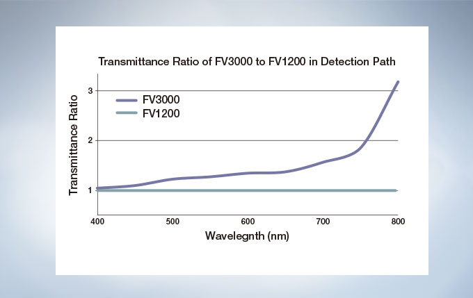
The FV3000 is a fully spectral series of confocal microscope. TruSpectral detection delivers improved overall transmission and sensitivity. The high signal-to-noise ratio results in excellent multi-color confocal imaging capabilities.
Enhanced Quantum Efficiency
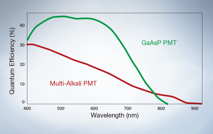
The GaAsP Photomultiplier Tubes (PMTs) in the FV3000’s high sensitivity detector (HSD) enable users to view samples whose emission is too weak to view with conventional detection methods. The GaAsP PMT unit incorporates two channels with a maximum quantum efficiency of 45%, and Peltier cooling that reduces background noise by 20% for high S/N ratio images under very low excitation light.
Multichannel TruSpectral Detection with Sixteen-Channel Unmixing
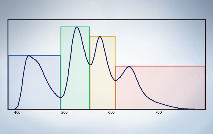
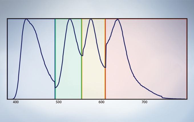
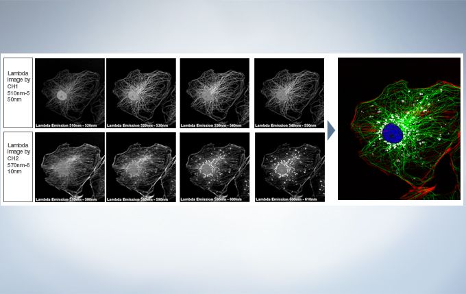
TruSpectral technology’s efficient design and software enable spectral detectors to run in multichannel mode for both live and post-processing spectral unmixing with a multichannel lambda mode. The multichannel mode facilitates constant spectral unmixing during live cell experiments, separating complex fluorescence during acquisition. With up to four different dynamic ranges from the four different channels of array, bright and dim spectral signals can be separated by independently adjusting the sensitivity of each detector.
Spectral Unmixing
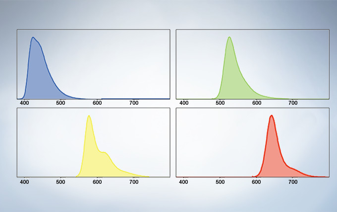
The deconvolution algorithm enables overlapping spectra to be separated based on the spectral information from lambda stack images. The fluorescence cross-talk between the channels can be eliminated by the unmixing algorithm during both image acquisition and post acquisition processing.
Live Spectral Unmixing with TruSpectral Detection and Real-Time Processing
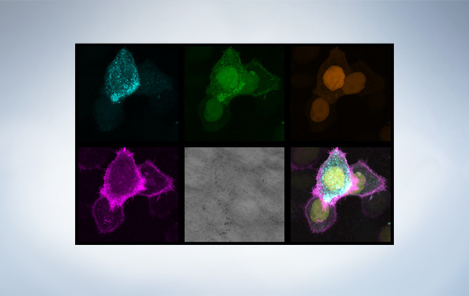
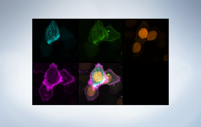
The power of TruSpectral detection plus multichannel mode means live spectral unmixing can be performed during image acquisition. Complex, overlapping spectra can be processed in real time.
Live image before unmixing of CFP (endosomes, blue), mAmetrine (plasma membrane, green), mKO (nucleus, orange) and mKeima (F-actin, purple) during time-lapse imaging. Image data courtesy of Dr. Kazuhiro Aoki, Dr. Michiyuki Matsuda, Graduate School of Medicine, Kyoto Uni
Live blind unmixed image. Image data courtesy of Dr. Kazuhiro Aoki, Dr. Michiyuki Matsuda, Graduate School of Medicine, Kyoto Un
Live 3D Rendering
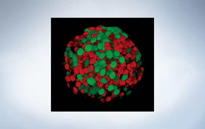
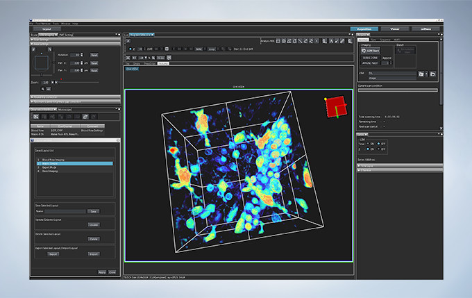
See your data unfold in real time with the live 3D image display function of the FV3000 software. 3D images can be constructed during image acquisition and shown as live images.
Fucci induced Spheroid of HT29 cell line Yuji Mishima, Ph.D., Kiyohiko Hatake M.D., Ph.D. Clinical Chemotherapy, Cancer Chemotherapy Center, Japanese Foundation for Cancer Research.
Macro to Micro Imaging and Super Resolution
Macro to Micro Observation
Finding areas of interest in samples can be challenging. The confocal optical design of the FV3000 series supports macro to micro imaging from 1.25X up to 150X, so users can quickly switch from low magnification overview observation to high-magnification, detailed observation of regions of interest. Users can employ image stitching at both macro and micro levels to generate overview images that show samples in context.
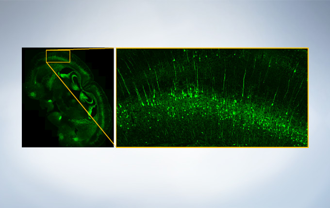
A stitched image of a coronal section (30 μm thickness) from an adult YFP-H mouse cerebrum acquired with 20X objective (UPLSAPO20X). Image data courtesy of Takako Kogure and Atsushi Miyawaki, Cell Function Dynamics, Brain Science Institute of RIKEN.
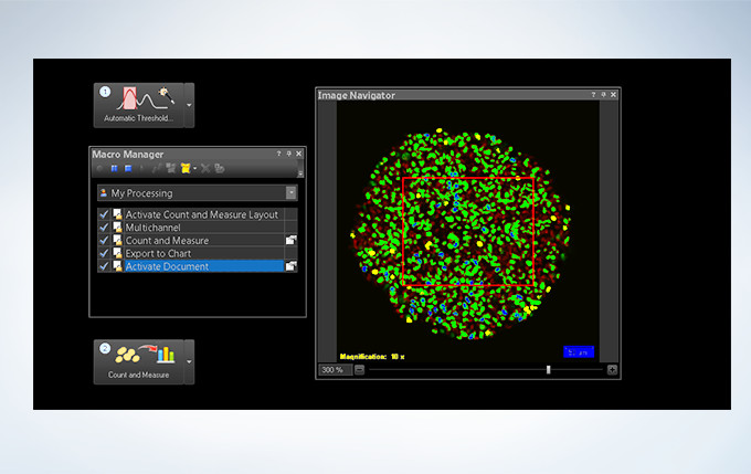
Powerful One-Click Macro Analysis with cellSens
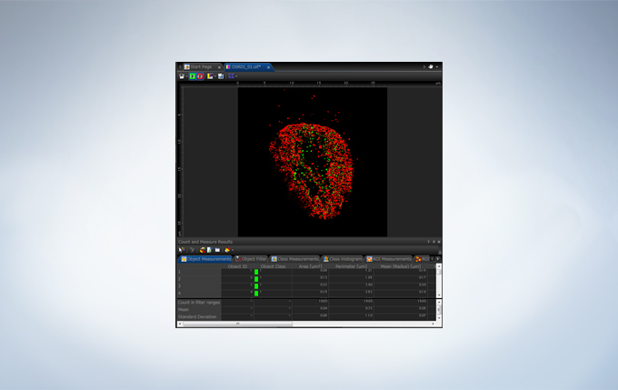
Images alone are not enough; with integrated cellSens Count and Measure analysis, the FV3000 Series can optimize images with deconvolution and analyze them with one-click macro functionality for a broad range of morphological measurements.
A spheroid image of a NMuMG cell line expressing Fucci2. Image data courtesy of Atsushi Miyawaki, Cell Function Dynamics, Brain Science Institute of RIKEN.
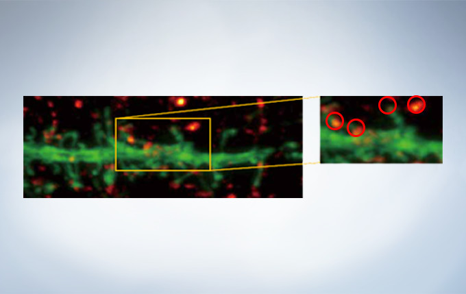
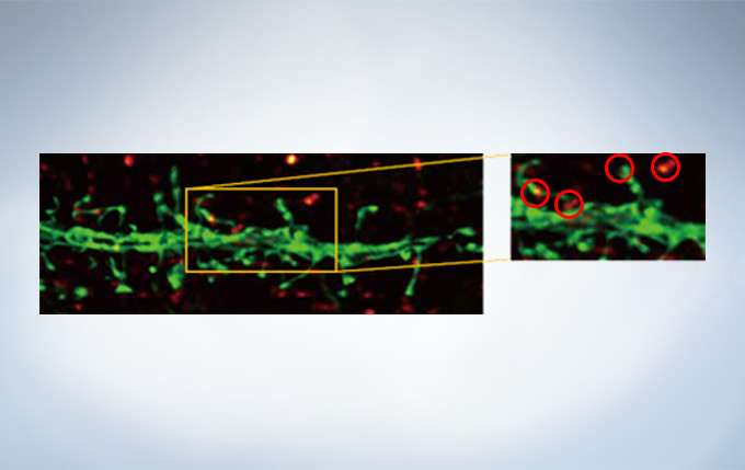
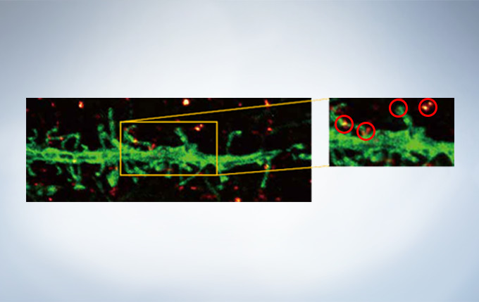
Olympus’ widely applicable super resolution method requires no special fluorophores and works for a wide range of samples. Ideal for colocalization analysis, the Olympus Super Resolution imaging module can acquire four fluorescent signals either sequentially or simultaneously with a resolution of approximately 120 nm*, nearly doubling the resolution of typical confocal microscopy. The imaging module is easy to use with minimal user training and can be added to any confocal system, making it a truly accessible method for achieving super resolution. * Subject to objective magnification, numerical aperture, excitation and emission wavelength, and experiment conditions.
Secondary antibody labels against GFP (Alexa Fluor 488, neurons) and SV2 (Alexa Fluor 565, red). Sample courtesy of Dr. Ed Boyden and Dr. Fei Chen, MIT.
0.5 AU Confocal Image0.5 AU Confocal Image Deconvolved with cellSens Advanced DeconvolutionOlympus Super Resolution Plus cellSens Advanced Deconvolution. Note clear separation of punctate stains with OSR.
Deconvolution
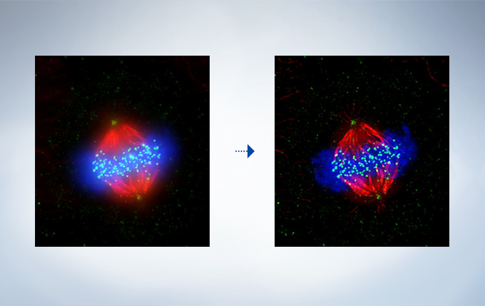
The optional constrained iterative deconvolution function improves the resolution, contrast, and dynamic ranges of confocal images obtained by the FV3000. The deconvolution function can be combined with Olympus Super Resolution (FV-OSR) to improve the z-axis resolution of the deconvolved images.
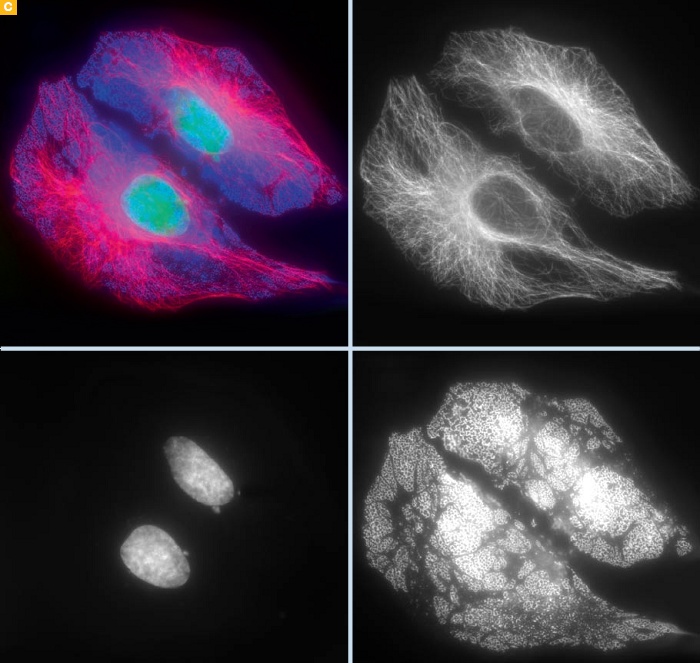
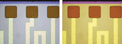
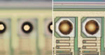
(Left) Original Image, (Right) Deconvolved Image
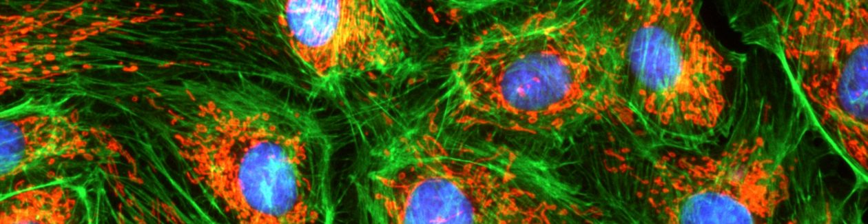
Cell line: HeLa (human cervical cancer cell line) Immunostaining: Hec1 staining (green, Alexa Fluor 488), α-tubulin staining (red, Alexa Fluor 568),DAPI staining (blue) Mitotic spindle and kinetochores are stained with anti-α-tubulin (red) and anti-Hec1 (green) antibodies, respectively. Chromosomes interact with microtubules of the mitotic spindle via kinetochores (protein structures assembled on the centromere region of chromosomes.) Image data courtesy of Masanori Ikeda and Kozo Tanaka, Department of Molecular Oncology, Institute of Development, Aging and Cancer, Tohoku University.
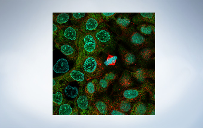
COS7 cells, triple staining, DAPI (cyan), Actin Bodipy-FL(green), Tubulin AF568 (red) Image data courtesy of J. Doehner and U. Ziegler, Center for Image Analysis and Microscopy, University of Zurich
Image Analysis
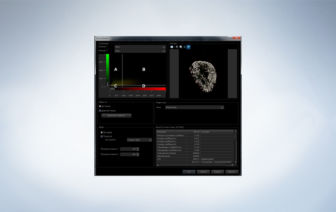
The FV3000 incorporates various optional analysis functions to complete the workflow from image acquisition through data analysis. The Count and Measure solution enables the measurement of the number, size, luminosity, and morphology of the segments. Colocalization enables the analysis of overlapping fluorescent spectra.
Increase Productivity with High Speed Imaging
Galvanometer and Hybrid Galvo/Resonant Scanner
Users have their choice of two different types of scan units: galvanometer only with the FV3000 or hybrid galvanometer/resonant with the FV3000RS. The hybrid scan unit has a galvanometer scanner for high-precision scanning, as well as a resonant scanner that is ideal for high-speed imaging. With the galvanometer scanner and Olympus super resolution technology (FV-OSR), users can obtain resolutions down to 120nm with a high signal-to-noise ratio. The galvanometer scanner also features flexible scanning options, including precise tornado scanning as well as multipoint stimulation with 100ms switching time. The galvanometer scanner can image up to 16 frames per second. By switching to the resonant scanner, users can capture 30 frames per second with a full field of view at 512 x 512 pixels. By clipping down to 512 x 32 pixels, the resonant scanner can capture up to 438 frames per second to capture critical live physiological events such as calcium ion flux.
No Compromise between Speed and Field of View
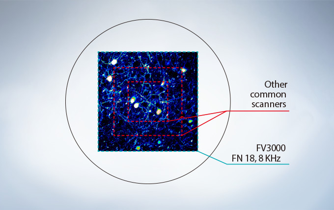
Many high-speed scanning methods restrict the field of view, limiting their usefulness for examining large areas with multiple cells. The FV3000 series’ resonant scanner maintains a full 1X field of view, even at a video rate of 30 frames per second. B clipping the Y axis, additional speeds up to 438 frames per second can be achieved.
Most resonant scanners force a trade-off between speed and field of view. FLUOVIEW systems are optimized to maintain the field of view with even signal intensity so dynamic samples (e.g. calcium imaging) can be seen in the broad context of their cells and tissues. The image above shows examples of the clipped fields of view required in other resonant scanning systems.
Platelets bound to a thrombosis in the blood vessel of a mouse. Images taken at 30 fps in full frame by resonant scanner with 2 CH GaAsP PMTs.
Image data courtesy of Dr. Takuya Hiratsuka, Dr. Michiyuki Matsuda, Graduate School of Biostudies, Kyoto University.
A431 cells fixed with methanol labeled with Abcam Anti-ERK1 + ERK2 antibody (Alexa Fluor 488) ab208564 and Anti-alpha Tubulin antibody (Alexa Fluor 594) ab195889 and DAPI. Sample courtesy of Abcam.
Optimized for Live Cell Imaging
Resonant scanning greatly reduces photobleaching and phototoxicity compared to standard galvanometer scans by preventing the excitation of fluorophores into triplet states that create reactive oxygen species. These features make live cell experiments more robust and reliable. The FV3000 series has complete laser intensity control from low to high range, enabling the system to use the minimum required amount of laser power on samples. The optional laser power monitor provides consistent laser power during long-term time-lapse imaging across multiple days.
Ratio Imaging and Intensity Modulated Display (IMD)
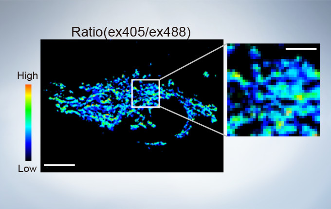
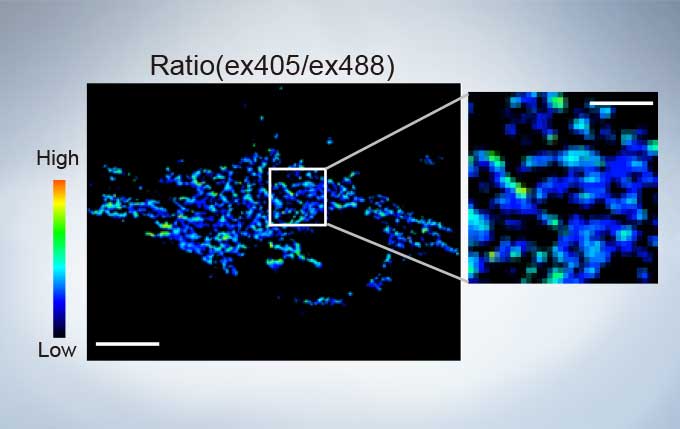
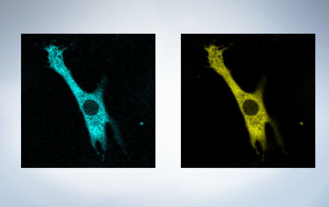
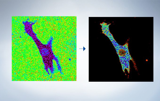
The FV3000’s ratio imaging analysis function includes an Intensity Modulated Display (IMD) function in the software that displays quantitative fluorescence ratio changes during both standard and high-speed acquisitions. This function is particularly useful for calcium and FRET imaging where a pure ratio display provides poor contrast in background areas.
sGFP1-mito reveals heterogeneity in mitochondrial thermogenesis in HeLa cells. The images of ratio (ex 405 nm/ex 488 nm) in tsGFP1-mito-expressing cells before and after CCCP treatment at 37 °C. Scale bars indicate 10 μm (whole image) and 3 μm (inset). Image data courtesy of Shigeki Kiyonaka Ph,D, Yasuo Mori Ph,D Molecular Biology Field, Department of Synthetic Chemistry and Biological Chemistry, Kyoto University.(Left) CFP, (Right) YFP FRET
(Left) Raw CFP/YFP ratio, (Right) IMD of CFP/YFP ratio
Cardiomyoctye Image data courtesy of Yusuke Niino and Atsushi Miyawaki, Cell Function Dynamics, Brain Science Institute of RIKEN.
Rolling Average Processing
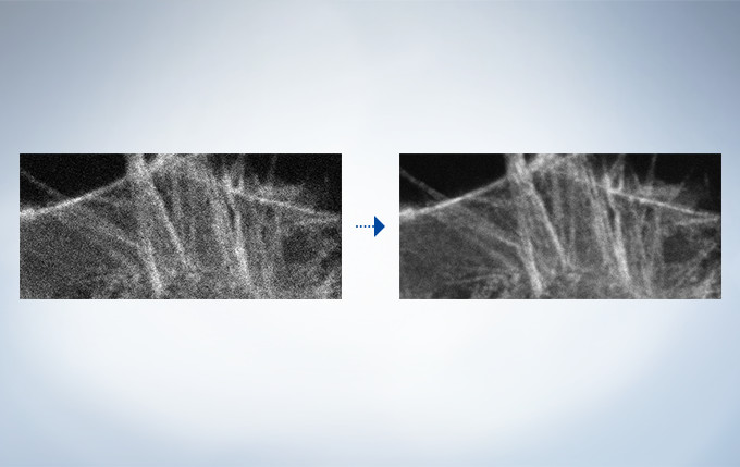
High-speed scanning at low laser power to avoid phototoxicity often decreases the signal-to-noise ratio. With rolling average post-processing, users have the flexibility to adjust high-speed time-lapse images while maintaining the time scale and keeping the original data.
(Left) Raw 30 fps data acquired at low laser power (0.05%, 488 nm). (Right) Rolling average processing (10 frame) on 30 fps data acquired at low laser power.
Object Tracking
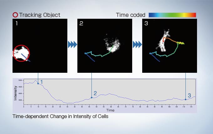
In time-lapse imaging, moving objects can be automatically detected, tracked, and analyzed. cellSens software’s tracking function provides a powerful and intuitive tool to quantify dynamic processes such as cell movement and division.
Bioluminescence of RA-induced differentiating cells at day 12 from Bmal1:luc stably transfected ES cells Image data courtesy of: Kazuhiro Yagita, M.D. Ph.D. Department of Physiology and Systems Bioscience, Kyoto Prefectural University of Medicine Reference: Proc Natl Acad Sci U S A. 107(8): 3846–3851(2010)
Accurate Time-lapse Imaging
Maintain Focus with Z-Drift Compensation (ZDC) System
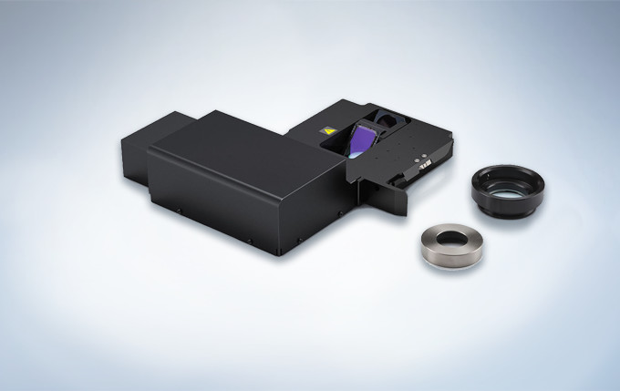
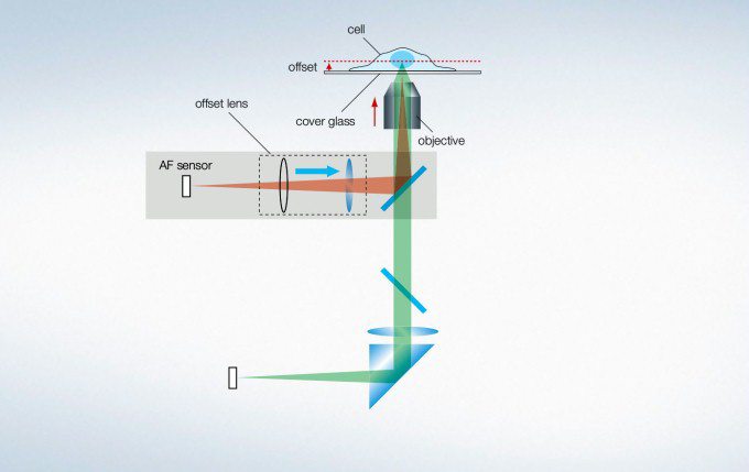
The IX3-ZDC2 Z-drift compensator uses minimally-phototoxic infrared light (laser class 1) to identify the location of the sample plane. One-shot autofocus (AF) mode enables several focus positions to be set as desired for deeper samples, enabling efficient Z-stack acquisitions in multiposition experiments. The continuous AF mode keeps the desired plane of observation precisely in focus, avoiding focus drift due to temperature changes or the addition of reagents, making it ideal for measurements that require more stringent focusing. Furthermore, the increased optical offset enables continuous AF with plastic vessels or with dry objectives. The Z-drift compensator is also compatible with silicone objectives (in AF mode).
Stage Control for Multi-Area Time-lapse, Microplate, and Stitching
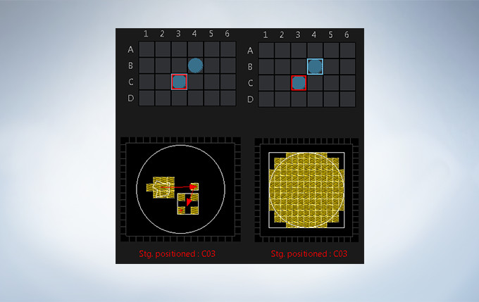
Multi-area time-lapse and stitching provide robust and accurate time-lapse data, and enable users to generate detailed overview images to see their data in context. The well navigator function provides sophisticated, intuitive controls for a wide range of cell culture vessels and custom plates.
Stable Time-Lapse Imaging with the IX83 Microscope
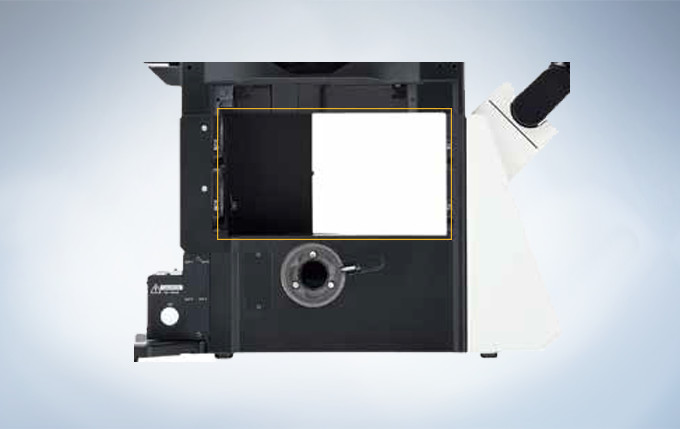
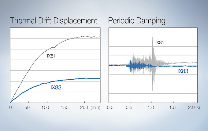
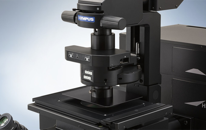
A Z-drive guide installed near the revolving nosepiece combines high thermal rigidity with the stability of a wraparound structure to significantly reduce the impact of heat and vibration and improve the quality of time-lapse imaging.
Hard Disk Recording
The microscope comes equipped with a hard-disk drive (HDD) recording function. The images are stored automatically in the HDD. Large volumes of data, such as those obtained from long-term time-lapse imaging, can be easily collected.
High Contrast under Bright Conditions
The umbra unit is designed specifically for fluorescence observation under bright room conditions. It efficiently blocks out room light, enhances the contrast of fluorescence, and enables clear fluorescence observation without the need for a dark room.
Reduce Complexity with the Sequence Manager
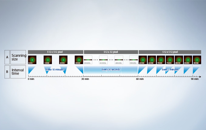
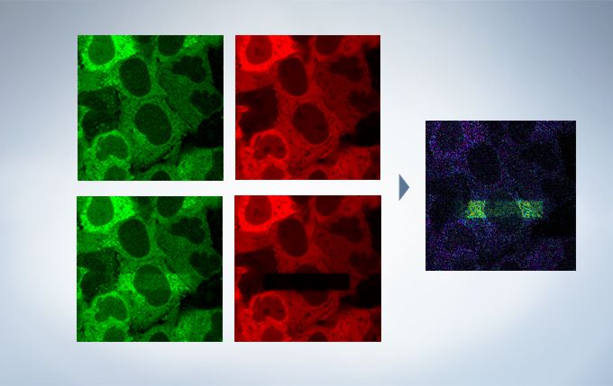
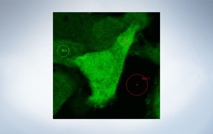
With the Sequence Manager software module, complex protocols are handled with ease and accurate timing. Multi-day time-lapse experiments are controlled with microsecond scan accuracy and millisecond sequence execution accuracy. Various protocols, such as time-lapse with different time intervals, switching between high and low magnification, and photo-stimulation between imaging by FRAP or FRET (acceptor photobleaching), can be performed.
Life Science Analysis
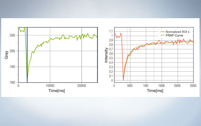
The cellSens Life Science Analysis module enables analysis of images from FRAP or FRET experiments. In FRAP, τ/2 and the Mobile/ Immobile fraction can be estimated by fitting the curve of luminosity change caused by fluorescence recovery after bleaching. FRET enables the measurement of FRET efficiency by acceptor photobleaching, ratio imaging, and sensitized emission.
Superior Objectives
Silicone Immersion Objectives for Live Cell Imaging Deliver High-Resolution Observation at Depth
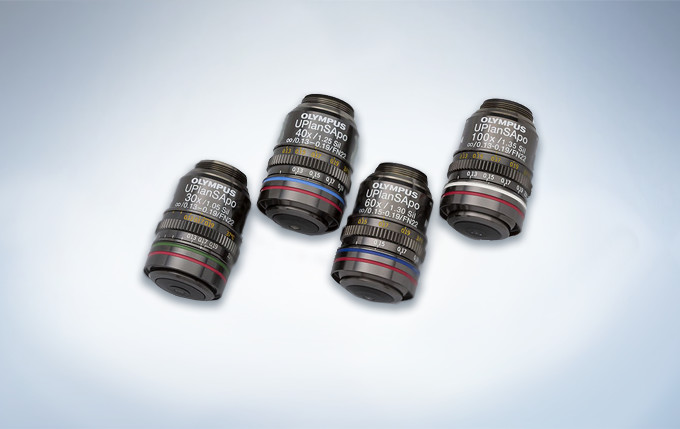
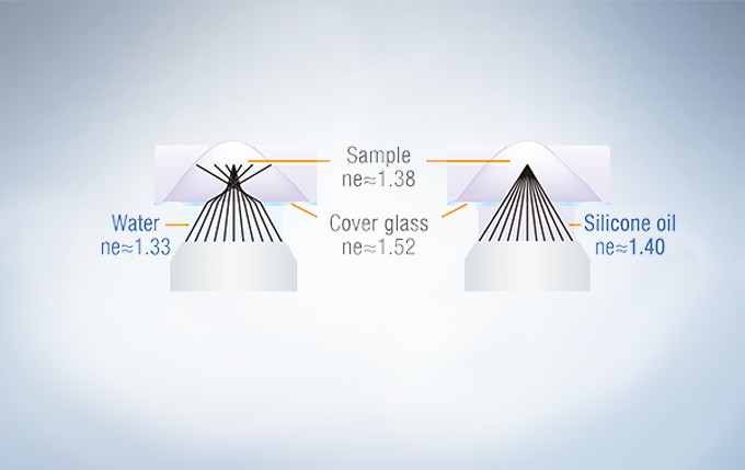
Olympus offers four high NA silicone immersion objectives that deliver excellent performance for live cell imaging. The refractive index of silicone oil (ne≈1.40) is close to that of living tissue (ne≈1.38), enabling high-resolution observations deep inside living tissue with minimal spherical aberration caused by refractive index mismatch. Silicone oil does not dry out or harden, so there is never a need to refill oil, making it ideal for extended time-lapse observations.
Water immersion objective (Left), Silicone immersion objective (Right)
In deep tissue observation, image quality depends on keeping the refractive index of the sample and immersion medium as close to each other as possible. When working with a silicone immersion objective, the difference between the refractive index of the samples and silicone oil is minimal, thus enabling brighter fluorescence images with higher resolution for deep tissue observation.
UPLSAPO30XS: For a broader view and greater depth Magnification: 30X, NA: 1.05 (silicone oil immersion), W.D.: 0.8 mm, cover glass thickness: 0.13 – 0.19 mm, operating temperature: 23 – 37 °C
UPLSAPO40XS : For a good balance between field of view and resolution Magnification: 40X, NA: 1.25 (silicone oil immersion), W.D.: 0.3 mm, cover glass thickness: 0.13 – 0.19 mm, operating temperature: 23 – 37 °C
UPLSAPO60XS2: For 3D observations with superior resolution Magnification: 60X, NA: 1.30 (silicone oil immersion), W.D.: 0.3 mm, cover glass thickness: 0.15 – 0.19 mm, operating temperature: 23 – 37 °C
UPLSAPO100XS: For greater brightness at depth in closely defined regions Magnification: 100X, NA: 1.35 (silicone oil immersion), W.D.: 0.2 mm, cover glass thickness: 0.13 – 0.19 mm, operating temperature: 23 – 37 °C
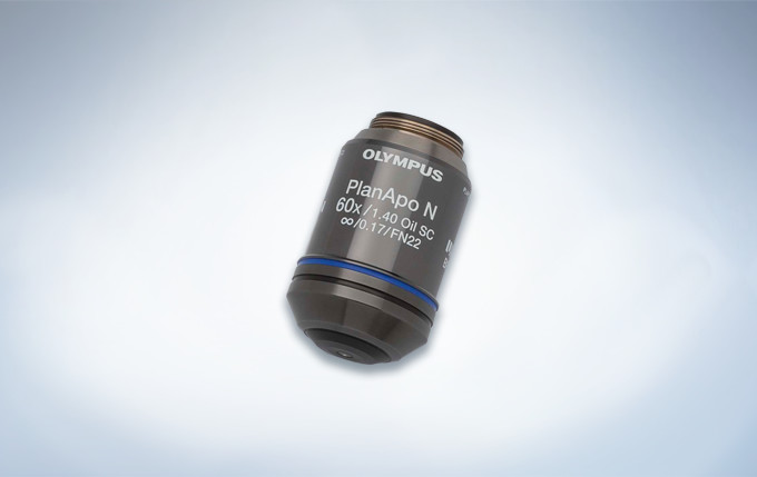
PLAPON60XOSC2: Enhance the Reliability of Colocalization Analysis with a Low Chromatic Aberration Objective
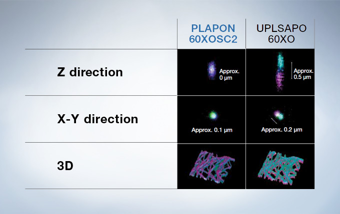
This oil immersion objective minimizes lateral and axial chromatic aberration in the 405–650 nm spectrum. Colocalization images are acquired reliably and images are measured with superior positional accuracy. The objective also compensates for chromatic aberration through near infrared up to 850 nm, making it the ideal choice for quantitative imaging.
Low Chromatic Aberration Objective Magnification: 60X NA: 1.4 (oil immersion) W.D.: 0.12 mm Chromatic aberration compensation range: 405 – 650 nm Optical data provided for each objective.
Performance Comparison of the PLAPON60XOSC2 and the UPLSAPO60XO
Reduce Spherical Aberration
The correction collar adjusts the lens position of objectives to correct the spherical aberration caused by refractive index mismatch, resulting in the improvement of image quality, such as resolution, brightness and contrast. The correction collar is especially necessary for objectives with high NA when they are used for super resolution imaging, because they are greatly affected by spherical aberration. The remote correction collar unit is useful for easy adjustment and improvement of the image quality, and operable on all UIS2 objectives which have a correction collar.
Choose the Frame That Suits Your Application
Inverted microscope
Suitable for observing cells cultured in a vessel.
The Z-drift compensator enables time-lapse observations that remain in focus.
Maintain the environmental conditions of cultured cells by adding a stage-top or full enclosure incubator.
Upright microscope (configured for imaging)
Optimized for fixed tissue and glass slide specimens.
Motorized 7-position nosepiece and condenser enable automated transitions from low to high magnification.
Upright microscope (configured for electrophysiology)
Ample space around the objectives enables patch-clamp devices to be installed.
Add additional space by lowering the stage position for experiments that require large sample handling.
Swing and slider nosepieces are available so objectives can be easily changed without interfering with the patch-clamp set-up.
Intuitive Software
Customizable and saveable layouts make it easy to tailor the interface to your workflow and experiment needs, from basic to complex.
Layout
Start by selecting your preferred display with specific tools for basic to complex acquisition.
Acquisition Condition
Reload settings that were ideal for your last experiment to provide consistency.
Acquisition
Activate basic to complex acquisitions with live ratio, intensity modulated display, quantitative region of interest (ROI) graphing or spectral unmixing display, and data backup for added security.
Viewer
Review data as it is generated. Generate 3D and 4D views and animations to explore and share data in depth.
Analysis
Extract data from images using online or offline processing. Analytical tools include Olympus super resolution technology (FV-OSR) and powerful cellSens software with features such as deconvolution, filtering, count and measure, and one-click macros.
LEXT OLS4500은 광학 현미경, 레이저 현미경(LSM), 프로브 현미경(SPM)을 한 대에 결합한 복합 현미경입니다. 관찰 배율은 수십 배에서 수백만 배까지 광범위한 영역을 커버하고 관찰 포인트를 잃는 일 없이 원활하게 밀리미터부터 나노미터까지 관찰 및 측정이 가능합니다.
OLS4500이 실현하는 새로운 솔루션
한번 잡은 타겟은 절대 놓치지 않는다.
전동 리볼버로 배율, 관찰 방법 전환
저배율에서 고배율 관찰이 가능한 4 개의 대물 렌즈와 SPM 장치를 전동 리볼버에 장착하여 배율과 관찰 방법을 원활하게 전환 할 수 있어 관찰 대상을 잃을 일이 없이 바로 나노미터까지 검색 할 수 있는 현미경입니다.
광 범위의 배율과 다양한 관찰 방법으로 관찰 대상을 쉽게 발견 할 수 있습니다.
첨단 광학 기술이 뒷받침된 다양한 관찰 방법과 저배율부터 고배율까지 관찰 대상을 쉽게 찾을 수 있습니다. 또한 광학 현미경으로는 보이지 않는 관찰 대상을 레이저 현미경으로 찾을 수 있습니다. 레이저 미분 간섭 (DIC) 관찰에서는 나노 수준의 미세 요철의 라이브 관찰도 가능합니다.
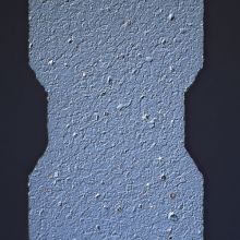
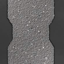
미분간섭 (DIC) 관찰
명시야 관찰( IC 패턴)
레이저 미분간섭(DIC) 관찰
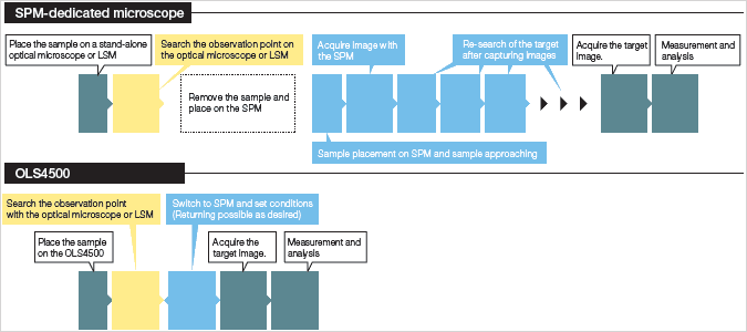
샘플 세팅부터 이미지 획득까지, 작업시간을 획기적으로 단축
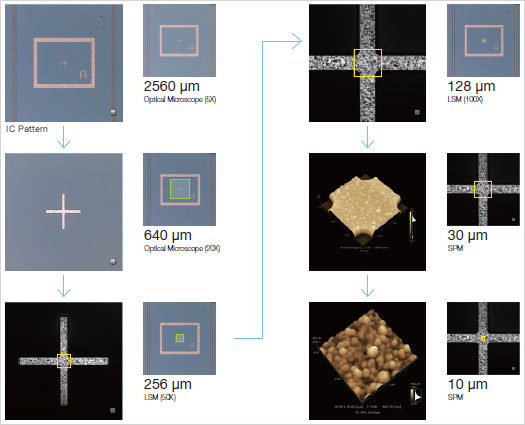
샘플 세팅 이후의 모든 작업을 1대의 장치로 수행 할 수 있습니다. 관찰대상을 신속, 정확하게 SPM 현미경 모드로 가져올 수 있기 때문에, 한 번의 스캐닝 영역 내에서 원하는 SPM 이미지를 얻을 수 있습니다.
일체형이기 때문에 샘플을 옮길 필요 없이 배율 및 관찰 방법을 교체하여 하나의 현미경으로 유연하게 대응 가능합니다.
OLS4500은 광학 현미경, 레이저 현미경, 프로브 현미경의 일체형이기 때문에 샘플을 옮길 필요 없이 세 가지의 현미경을 자유 자재로 전환하며 관찰 및 평가가 가능합니다. 각각이 가진 뛰어난 기능으로 효율적인 최적의 결과 값을 얻을 수 있습니다.
OLS4500에서 가능한 원할한 관찰과 측정
관심 영역을 바로 찾는 것이 가능
광학 현미경의 다양한 관찰법을 이용하여 빠르게 관찰 대상을 찾아낼 수 있습니다.
광원으로 백색 LED를 사용하기 때문에, 색 재현성이 뛰어난 고해상도 컬러 이미지를 볼 수 있습니다. 4개의 대물 렌즈로 저배율에서 고배율까지 관찰이 가능합니다. OLS4500은 광학 현미경의 기능을 최대한 활용하여 가장 많이 사용되는 명시야관찰 (BF)을 비롯해 미세한 요철에 컨트라스트를 넣어 입체적으로 시각화하는 미분간섭관찰 (DIC), 샘플의 편광특성이 색으로 표현되는 간이 편광 관찰이 가능합니다. 또한 노출시간을 바꾸어 여러장의 이미지를 촬영, 합성 하는 것으로 밸런스가 좋은 밝기와 향상된 텍스처의 이미지를 보여주는 HDR기능(High Dynamic Range)을 이용 할 수 있습니다. 다양한 관찰 방법으로 신속하게 관심 영역을 찾을 수 있습니다.
가장 널리 사용되는 관찰 방법입니다. 자연스러운 이미지와 사실적인 칼라 재현. 컨트라스트가 있는 샘플의 관찰에 적합합니다.
명시야에서는 보이지 않는 샘플의 미세한 단차를 시각화합니다. 금속조직, 하드디스크 및 웨이퍼 연마 표면 같은 거울위의 스크레치나 이물질 관찰에 적합합니다.
편광 (특정 진동 방향을 갖는 빛)을 조사하여 샘플의 편광 특성 (굴절률 등)을 시각화합니다. 금속 조직, 무기물, 반도체 재료 등의 관찰에 적합합니다.
노출 시간을 바꾸어 여러 장의 사진을 찍어 합성하는 것으로, 밝은 부분, 어두운 부분을 균형있게 볼 수 있습니다. 또한 텍스처 (표면 상태)를 강조함으로써 세밀한 관찰이 가능합니다.
LSM은 광학 현미경으로는 보이지 않는 것을 가능하게 합니다.
405nm 짧은 파장의 레이저 광원과 높은 N.A의 전용 대물렌즈를 사용하여, 높은 평면 분해능을 가집니다. 광학 현미경으로는 보이지 않았던 관찰대상을 선명한 이미지로 관찰하는 것이 가능합니다. 레이저 미분간섭(DIC)은 나노미터의 마이크로영역 표면의 실시간 관찰도 가능합니다.
명시야 관찰
(유리판 위의 이물질)
레이저 DIC 관찰
【접근법】관심 영역에 정확하고 빠르게 접근하여 SPM으로 관찰
관찰 대상을 놓치지 않고 원할하게 관찰 가능
저배율에서 고배율 관찰이 가능한 4개의 대물 렌즈와 소형 SPM 장치를 전동 리볼버에 장착. 광학현미경 또는 레이저 현미경 50배, 100배의 실시간 관찰에서는 SPM 스캔범위가 시야의 중심에 표시되므로 관찰 포인트를 이 위치에 맞춘 후, 프로브현미경으로 전환 하는 것만으로 관찰대상에 정확하게 접근 할 수 있습니다. 따라서 원하는 이미지를 한번의 SPM 스캔으로 획득할 수 있고, 작업의 효율성과 캔틸레버의 소모를 줄일 수 있습니다.
SPM 관찰로 쉽게 전환 하기 위한 안내 기능
캔틸레버 설치, 스캔 범위 설정 등 프로브 현미경으로 관찰하는 데 필요한 준비는 안내 화면에 따라 수행 할 수 있어, 경험이 적은 사람이라도 안심하고 작업을 할 수 있습니다.
【나노미터 접근 측정】간단한 조작으로 빠른 측정이 가능
노이즈 감소를 위해 새롭게 개발된 SPM 헤드
OLS4500에서는 전동 리볼버에 장착하는 대물 렌즈 형 SPM 헤드를 사용. 대물 렌즈와 캔틸레버 끝을 동축, 동초점으로 배치하여, SPM 관찰로 전환 하더라도 관찰 포인트를 잃지 않습니다. 또한 새로 개발한 소형 SPM 헤드는 강성을 높여 기존제품보다 이미지의 노이즈를 줄이고 응답성을 향상 시켰습니다.
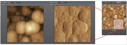
네비게이터 기능으로 SPM 이미지를 자유자재로 확대
네비게이터 기능은 프로브 현미경에서 얻은 이미지의 필요한 부분을 더 크게 확대하여 관찰 할 수 있습니다. 이미지에서 확대 범위를 커서로 설정하여 스캔을 시작하는 것 만으로 원하는 SPM 이미지를 얻을 수 있습니다. 스캔 범위는 자유롭게 설정할 수 있으므로 관찰 · 측정 효율성이 크게 향상됩니다.
네비게이터 기능 10μmx10μm의 이미지에서 3.5μmx3.5μm의 범위를 확대
다양한 요구 사항을 충족하는 분석 기능
곡률 측정 (하드 디스크 핏)
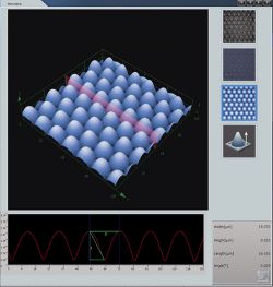
각종 측정 모드에서 얻은 이미지는 목적에 따른 분석이 가능하며, 측정 결과는 CSV 형식으로 출력 할 수 있습니다. OLS4500는 다음의 분석 기능이 있습니다.
단면 형상 분석 (곡률 측정, 협각 측정)
거칠기 분석
형태 분석 (면적, 표면적, 체적, 높이, 히스토그램 값, 베어링 비율 값)
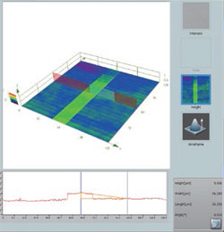
평균 단차 측정 (라인 지정, 크기 지정)
입자 분석 (옵션)
가이드 화면으로 따라하기 쉬운 6개의 SPM 측정 모드
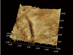
접촉 모드
캔틸레버와 샘플 사이에서 작동하는 반발력이 일정하게 되도록 제어하면서 캔틸레버를 정적으로 스캔하며 샘플의 높이를 이미지화 시키다. 힘 곡선 측정에도 사용 할 수 있습니다.
금속 얇은 필름
다이나믹 모드
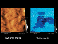
캔틸레버를 공진 주파수 근처에서 진동시켜 진폭이 일정하게 되도록 Z축 방향의 거리를 제어하는 것으로, 샘플의 높이를 이미지화 시킨다. 특히 고분자 화합물 같은 부드러운 표면 샘플 및 점착성이 있는 샘플에 적합합니다.
알루미늄 표면
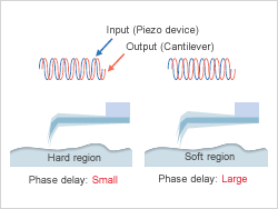
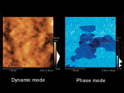
위상 모드
다이나믹 모드에서 스캐닝하는 동안 캔틸레버 진동의 위상 지연을 감지합니다. 샘플 표면의 물리적 특성의 차이를 이미지화 할 수 있습니다.
고분자 필름
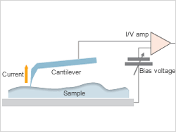
전류 모드
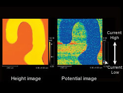
샘플에 바이어스 전압을 인가하여 캔틸레버와 샘플 사이에 흐르는 전류를 감지하여 이미지화시킵니다. 또한 I / V 측정도 가능합니다.
Si 기판위의 SiO2 패턴 샘플입니다. 높이 이미지 (왼쪽)으로 노랗게 보이는 부위가 SiO2입니다. 전류 이미지 (오른쪽)는 청색 (전류가 흐르지 않는 부위)에 표시되어 있습니다. 기판위에도 흐르지 않는 부분이 있다는 것을 알 수 있습니다.
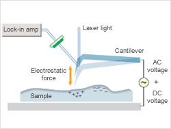
표면 전위 모드 (KFM)
전도성 캔틸레버를 이용하여 교류 전압을 인가하여 캔틸레버와 샘플 표면 사이에 작용하는 정전기의 힘을 감지하고 샘플 표면의 전위를 이미지화 시킵니다. KFM (Kelvin Force Microscope)라고도합니다.
자기 테이프 샘플. 전위 상은 수백 mV의 전위차가 샘플 표면에 분포되어 있음을 알 수 있습니다. 이러한 전위의 분포는 테이프 표면에 존재하는 윤활 층의 불규칙을 나타내고 있다고 간주 됩니다.
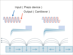
자력 모드 (MFM)
자력을 갖는 캔틸레버를 위상 모드에서 검사하여, 진동 하는 캔틸레버의 위상 지연을 감지하고 샘플 표면의 자기 정보를 이미지화 시킵니다. MFM (Magnetic Force Microscope)라고도 합니다.
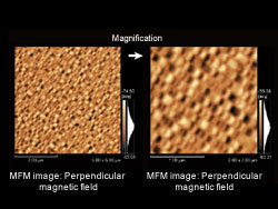
하드 디스크 표면 샘플. 자성의 분포를 이미지로 볼 수 있습니다.
레이저 현미경으로 다양한 샘플을 유연하게 대응
85°이상의 경사도 이미지
OLS4500의 높은 해상도와 405nm의 광학시스템에 맞게 설계된 전용렌즈의 채택으로 기존에 측정 불가능했던 급경사면의 이미지를 손쉽게 취득할 수 있습니다.
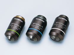
LEXT전용 대물 렌즈
급경사면의 면도칼
높은 분해능을 가진 마이크로 프로파일 측정
405nm의 단파장 레이저 빛과 높은 N.A의 전용 대물 렌즈 사용으로 최대 0.12μm의 평면 분해능을 실현. 샘플 표면의 서브 마이크론 측정이 가능합니다. 또한 고정밀 리니어 스케일과 올림푸스 만의 밝기 감지 기술은 서브 마이크론에서 수백 마이크론의 높이 차이를 감지 할 수 있습니다. 또한 레이저 현미경에 의한 측정은 측정기 2 가지 지표인 ‘정확도'(참값에 근접)과 ‘반복성'(편차의 작음) 모두의 성능을 보장하고 있습니다.
0.12 μm 선 과 공간 패턴
(MPLAPON50XLEXT)
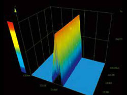
STEP 높이 표준 B 타입, PTB-5, 독일, 마이크로 전자 연구소 6nm 단차를 감지
광범위의 영역에서 임의의 캡처 이미지 지정
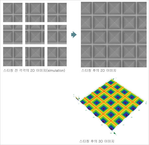
고배율의 이미지에서는 시야범위가 좁아지지만, 스티칭기능으로 최대625장까지 이미지를 붙여 높은 분해능과 넓은 시야범위로 이미지 데이터를 얻을 수 있습니다. 또한 넓은 시야 이미지로 3D 디스플레이 및 3D 측정이 가능합니다.
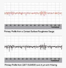
마이크로 영역의 표면 거칠기를 비접촉으로 측정
기존의 선 거칠기 측정에서 보다 정보량이 많은 평면 거칠기 측정이 가능
최근 산업 제품의 크기와 무게의 지속적인 감소로, 이를 구성하는 부품도 소형화 되고 있습니다. 이러한 경향은 표면 거칠기 측정뿐만 아니라, 형상 측정에서도 중요성이 증가하고 있습니다. 이러한 시장의 요구를 반영하여 ISO에서 규정하는 3D 표면 질감 측정 장치 (ISO 25178-6)의 목록에 LSM과 AFM을 추가했습니다. 이 비접촉 표면 거칠기 측정은 (삭제) 기존의 접촉 표면 거칠기 측정기와 같은 공식적인 평가 기준으로 인정된다는 것을 의미합니다. OLS4500은 ISO에 적합한 거칠기 파라미터를 제공합니다.
표면 거칠기 측정의 거칠기 분포와 특징을 자세히 파악
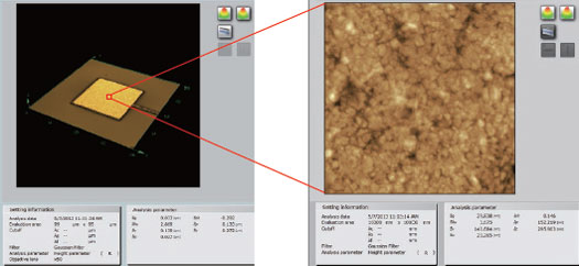
비접촉 표면 거칠기 측정은 평면 거칠기뿐만 아니라 선 거칠기를 얻을 수 있습니다. 표면 거칠기 측정은 샘플 표면에서 설정 한 영역의 분포와 특징을 파악할 수 있으며, 3D 이미지와 대조 한 평가가 가능합니다. OLS4500은 LSM 또는 SPM 기능을 사용하여 표면 거칠기를 측정 할 수 있습니다. 이 두 기능은 샘플 속성 혹은 관찰 목적에 따라 구분하여 사용할 수 있습니다.
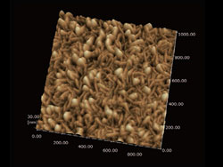
(좌) 레이저 현미경에 의한 표면 거칠기 (105μm x 105μm)본딩 패드 (우) 프로브 현미경에 의한 표면 거칠기 (10μm x 10μm)
LEXT OLS4500 파라미터
파라미터 호환성
OLS4100은 접촉식 표면 거칠기 측정기와 같은 거칠기 (2 차원) 파라미터를 보유하고 있습니다. 접촉식 표면 거칠기 측정기와 같은 조작성, 호환 측정 결과를 얻을 수 있습니다.
차세대 파라미터에 대응
OLS4500은 ISO25178 규격 거칠기 (3 차원) 파라미터를 보유하고 있습니다. 평면 영역에서 평가를 실시하는 것으로, 높은 신뢰성이 있는 분석이 가능합니다.
OLS4500의 현미경 기술
광학 현미경의 원리와 특징
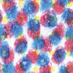
명시야 관찰은 색상 정보를 제공 합니다. 잉크젯 점.
가시 광선 영역 (400-800 nm의 파장)을 사용하여 광학 현미경 이미지를 1000배 정도의 배율로 관찰 할 수 있습니다. 광학 현미경의 특징은 샘플이 가지는 색을 그대로 관찰 할 수 있으며 관찰 방법을 바꾸는 것으로 요철을 강조하거나 물질의 특성 (편광 특성)을 이용한 관찰을 할 수 있다는 것 입니다. OLS4500에서는 다음 관찰 방법이 가능합니다.
간이 편광 관찰 편광(특정 진동 방향을 갖는 빛) 빛을 사용하여 샘플의 편광 속성을 시각화
레이저 스캐닝 현미경의 원리와 특징
마이크로 영역 때의 관찰과 측정이 가능한 LSM(Laser Scanning Microscope)
레이저 현미경의 고해상도 XY스캐닝(이미지)
광학 현미경의 평면 분해능은 사용하는 빛의 파장에 크게 의존합니다. 단파장의 레이저 빛을 사용하는 레이저 현미경은 가시 광선을 사용하는 기존의 현미경에 비해 평면 분해능이 뛰어납니다. OLS4500는 405nm의 단파장 반도체 레이저를 사용하며, 높은 개구 수 (NA) 전용 대물 렌즈, 공 초점 광학계를 결합하여 최대 0.12μm의 평면 분해능을 실현하고 있습니다. 또한 올림푸스 만의 2 차원 스캐너에 의한 XY 스캐닝 기능에서 최대 4096 픽셀 x 4096 픽셀의 고해상도 스캔을 가능하게 하고 있습니다.
뛰어난 높이 측정 능력
단차 측정
레이저 현미경은 단파장 반도체 레이저와 공 초점 광학계를 사용하여 초점이 맞는 반사광을 감지하고 초점이 맞지 않는 부분의 반사광은 제외됩니다. 정밀 리니어 스케일과 결합하여 정확한 3 차원 측정이 가능합니다.
프로브 현미경의 원리와 특징
나노 레벨의 세계를 시각화 하는 프로브 현미경(SPM : Scanning Probe Microscope)
프로브 현미경의 원리
끝 곡률이 10nm 정도의 미세한 탐침 (프로브)을 샘플 표면에 접근 시켜 샘플 사이에 발생하는 역학적 · 전기적 상호 작용을 감지하면서 스캐닝하여 3 차원 적으로 관찰하는 현미경을 총칭하여 프로브 현미경 (SPM)라고 합니다. 대표적인 것으로 탐침과 샘플 표면 사이에 작용하는 인력과 척력을 감지하여 스캔 이미지를 얻는 원자 힘 현미경 (AFM : Atomic Force Microscope)이 있습니다. 나노 수준에서 관찰하는 것으로, 샘플의 모습을 세밀하게 파악할 수 있습니다.
캔틸레버 스캐닝으로 나노를 관찰
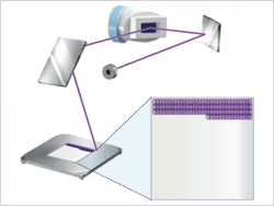
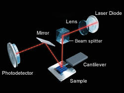
SPM Sensor의 광학 경로
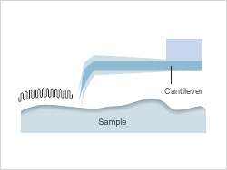
OLS4500은 끝에 탐침 (프로브)을 배치 한 캔틸레버의 미세한 굴곡 량 (변위)를 고감도로 검출하는 광 지렛대 방식을 사용. 레이저 빛을 캔틸레버 후면에 반사시켜 광 검출기의 일정한 위치에 맞게 압전 소자에서 Z축으로 구동시켜 미세한 Z축 방향의 변위를 정확하게 읽습니다.
다양한 모드에서 표면 형상과 물리적 이미지화
폴리머 필름
프로브 현미경의 다양한 모드는 샘플 표면 형상 관찰, 측정, 또한 물리적 특성의 분석이 가능합니다. OLS4500는 다음 모드를 지원합니다.
접촉 모드: 표면 형상을 이미지화 (딱딱한 표면)
다이나믹 모드: 표면 형상을 이미지화 (부드러운 표면, 점성이있는 표면)
위상 모드: 샘플 표면의 물리적 특성의 차이를 이미지화
전류 모드*: 프로브와 샘플 사이에 흐르는 전류를 감지하여 이미지화
표면 전위 모드 (KFM)*: 샘플 표면의 전위를 이미지화
자기력 모드 (MFM)*: 샘플 표면의 자기력 정보를 이미지화 * Optional.
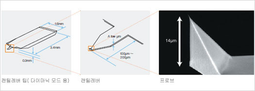
캔틸레버 : 고정밀, 고품질 이미지의 핵심
탐침 (프로브)은 길이 100μm에서 200μm 정도의 얇은 판 모양 캔틸레버 끝으로 형성되어 있습니다. 캔틸레버는 샘플에 따라 용수철 상수, 공진 주파수를 선택합니다. 스캔 반복에 따라 탐침 (프로브)은 마모하기 때문에 필요에 따라 혹은 정기적으로 캔틸레버 팁을 교체합니다.
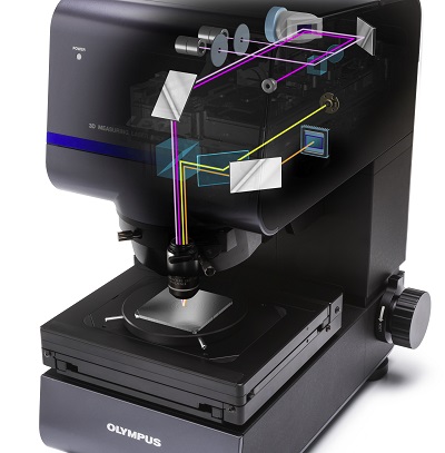
The OLS5000 laser confocal microscope precisely measures shape and surface roughness at the submicron level. Data acquisition that’s four times faster than our previous model delivers a significant boost to productivity.
High-resolution, precise imaging
With the capability to make accurate 3D measurements on a wide range of sample types, the system delivers reliable data for quality assurance and process control.
Excellent lateral resolution
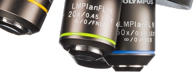
The 405 nm violet laser and dedicated high-NA objectives make it possible to capture fine patterns and defects that conventional optical microscopes, white-light interferometers, or red laser-based microscopes are unable to detect.
Red type (658 nm: 0.26 μm line & space)
Violet type (405 nm: 0.12 μm line & space)
Uniform measurement values
Dedicated LEXT objectives can accurately measure peripheral areas that would otherwise get distorted.
Conventional objectives
LEXT objectives
Newly developed MEMS Scanner
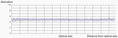
New MEMS scanner performs accurate X-Y scanning with low scan trace distortion and minimal optical aberrations.
4K scan technology
The 4K scan technology scans 4,096 pixels — four times more than our previous model — in the X-axis direction. The OLS5000 microscope can detect slopes that are almost vertical as well as very low steps without image correction.
Capturing the true shape
Because conventional laser microscopes use standard image processing techniques such as smoothing to eliminate noise, they sometimes lose accurately measured fine height irregularities along with the noise. The OLS5000 microscope employs Olympus’ Smart Judge algorithm to automatically detect only reliable data, facilitating accurate measurements without losing fine height irregularity data.
Designed for use in the steel, automotive, electronics, and other manufacturing industries, the GX53 microscope delivers crisp images that can be difficult to capture using conventional microscopy observation methods. When combined with OLYMPUS Stream image analysis software, the microscope streamlines the inspection process from observation to image analysis and reporting.
Fast Inspections, Advanced Functionality
Quickly observe, measure, and analyze metallurgical structures.
Advanced Analysis Tools
1. Combined observation methods produce exceptional images
2. Easily create panoramic images
3. Create all-in-focus images
4. Capture both bright and dark areas
Optimized for Material Science
1. Software designed for materials science
2. Metallurgical analysis that complies with industrial standards
Userfriendly
Even novice operators can comfortably make observations, analyze results, and create reports.
1. Easily restore microscope settings
2. User guidance helps simplify advanced analysis
3. Efficient report generation
Advanced Imaging Technology
Our proven optics and imaging technology deliver clear images and reliable results.
1. Reliable optical performance: wavefront aberration control
2. Clear images: image shading correction
3. Consistent color temperature: high-intensity white LED illumination
4. Precise measurements: auto calibration
Modular
Choose the components you need for your application.
1. Build your system your way: fully customizable system with a variety of optional components
The MX63 and MX63L microscope systems are optimized for high-quality inspections of wafers as large as 300 mm, flat panel displays, circuit boards, and other large samples. Their modular design enables you to choose the components you need to tailor the system to your application.
These ergonomic and user-friendly microscopes help increase throughput while keeping inspectors comfortable while they do their work. Combined with OLYMPUS Stream image analysis software, your entire workflow, from observation to report creation, can be simplified.
Functional
Leading-Edge Analysis Tools
The MX63 series’ versatile observation capabilities provide clear, sharp images so users can reliably detect defects in their samples. New illumination techniques and image acquisition options within OLYMPUS Stream image analysis software give users more choices for evaluating their samples and documenting their findings.
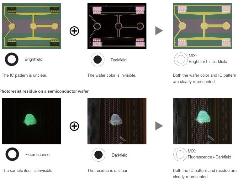
The Invisible Becomes Visible: MIX Observation and acquisition
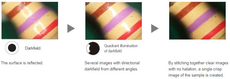
MIX observation technology produces unique observation images by combining darkfield with another observation method, such as brightfield, fluorescence, or polarization. MIX observation enables users to view defects that are difficult to see with conventional microscopes. The circular LED illuminator used for darkfield observation has a directional darkfield function where only one quadrant is illuminated at a given time. This reduces a sample’s halation and is useful for visualizing a sample’s surface texture.
Structure on semiconductor wafer
Condenser
Easily Create Panoramic Images: Instant MIA
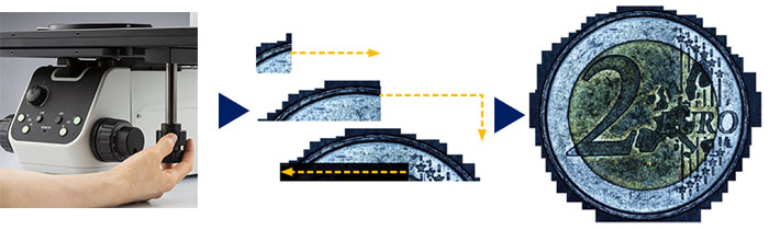
With multiple image alignment (MIA), users can stitch images together quickly and easily simply by moving the KY knobs on the manual stage—a motorized stage is not necessary. OLYMPUS Stream software uses pattern recognition to generate a panoramic image, giving users a wider field of view.
Instant MIA image of a coin
Create all-in-focus images: EFI
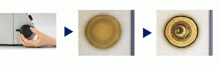
The Extended Focus Imaging (EFI) function within OLYMPUS Stream captures images of samples whose height extends beyond the depth of focus of the objective and stacks them together to create one image that is all in focus. EFI can be executed with either a manual or motorized Z-axis and creates a height map for easy structure visualization. It is also possible to construct an EFI image while offline within Stream Desktop.
Stud bump on an IC chip
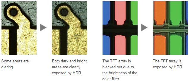
Capture Both Bright and Dark Areas Using HDR
Using advanced image processing, high dynamic range (HDR) adjusts for differences in brightness within an image to reduce glare. HDR improves the visual quality of digital images thereby helping to generate professional-looking reports.
From Basic Measurement to Advanced Analysis
Measurement is essential to quality and process control and inspection. With this in mind, even the entry-level OLYMPUS Stream software package includes a full menu of interactive measurement functions, with all measurement results saved with image files for further documentation. In addition, the OLYMPUS Stream Materials Solution offers an intuitive, workflow-oriented interface for complex image analysis. At the click of a button, image analysis tasks can be executed quickly and precisely. With a significant reduction in processing time for repeated tasks, operators can concentrate on the inspection at hand.
Efficient Report Creation
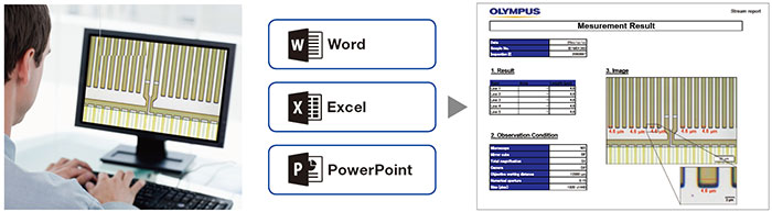
Creating a report can often take longer than capturing the image and taking the measurements. OLYMPUS Stream software provides intuitive report creation to repeatedly produce smart and sophisticated reports based on pre-defined templates. Editing is simple and reports can be exported to Microsoft Word or PowerPoint software. In addition, OLYMPUS Stream software’s reporting function enables digital zooming and magnification on acquired images. Report files are a reasonable size for easier data exchange by email.
Stand-Alone Camera Option
Using a DP22 or DP27 microscope camera, the MX63 series becomes an advanced stand-alone system. The cameras can be controlled via a compact box that requires only minimal space, helping users maximize their laboratory space while still capturing clear images and making basic measurements.
Advanced Designed to Support Cleanroom Conformity
The MX63 series is designed to work in a cleanroom and has features that help minimize the risk of contaminating or damaging samples. The system has an ergonomic design that helps keep users comfortable, even during prolonged use. The MX63 series complies with international specifications and standards, including SEMI S2/S8, CE, and UL.
Optional Wafer Loader Integration ― AL120 System*
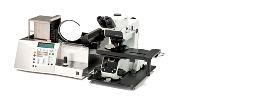
An optional wafer loader can be attached to MX63 series to safely transfer both silicon and compound semiconductor wafers from a cassette to the microscope stage without using tweezers or wands. Renowned performance and reliability enable safe, efficient front and back macro inspections while the loader helps improve productivity in the laboratory.
MX63 combined with the AL120 wafer loader (200 mm version)
Fast, Clean Inspections
The MX63 series delivers contamination-free wafer inspections. All motorized components are housed in a shielded structure, and antistatic processing is applied to the microscope frame, tubes, breath shield, and other parts. The rotation speed of the motorized nosepieces is faster and safer than manual nosepieces, decreasing the time between inspections while keeping the operator’s hands below the wafer, reducing potential contamination.
System Design Achieving Efficient Observations
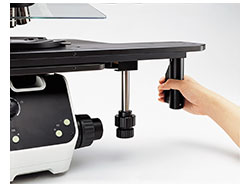
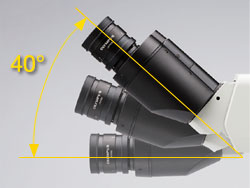
The XY stage is capable of both coarse and fine stage movements thanks to the combination of a built-in clutch and the XY knobs. The stage helps make observations efficient, even for large samples, such as 300 mm wafers. The tilting observation tube’s extensive range enables operators to sit at the microscope in a comfortable posture.
System Design Achieving Efficient Observations
The XY stage is capable of both coarse and fine stage movements thanks to the combination of a built-in clutch and the XY knobs. The stage helps make observations efficient, even for large samples, such as 300 mm wafers. The tilting observation tube’s extensive range enables operators to sit at the microscope in a comfortable posture.
Accepts All Wafer Sizes
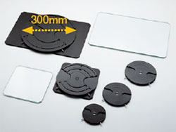
Wafer holders and glass plates
The system works with various types of 150–200 mm and 200–300 mm wafer holders and glass plates. Should the size of the wafters change on the production line, the microscope’s frame can be modified at minimal cost. With the MX63 series, different stages can be used to accommodate 75 mm, 100 mm, 125 mm, and 150 mm wafers on the inspection line.
청정도는 많은 산업, 제약 및 의료 장비 분야에서 매우 중요합니다.
청정도는 모든 제품 공정과 기술 구성요소의 기능 생명 주기에 영향을 미칠 수 있으며 모든 제품은 잔여물과 입자 검출에 대한 특정한 요구 사항을 가지고 있으므로 궁극적으로 제품 및 생산 공정의 품질 개선을 위해 사용될 수 있습니다.
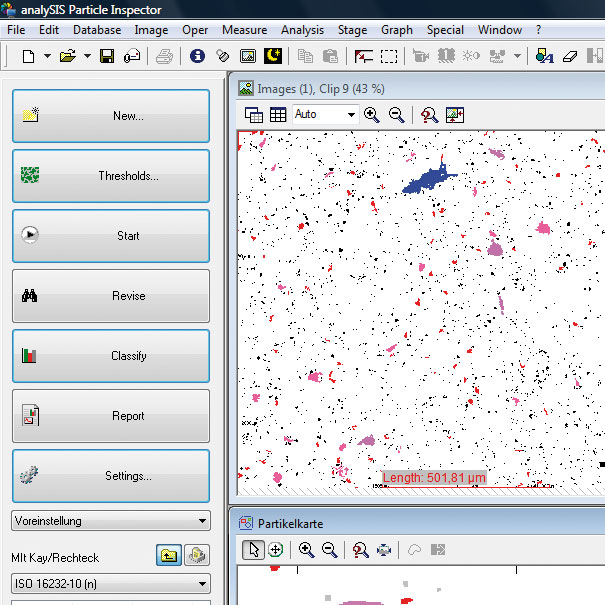
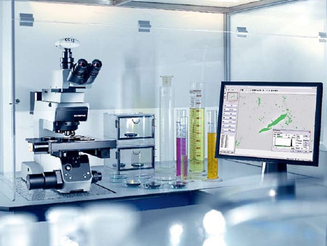
올림푸스 “Particle Inspector” 는 완전히 자동화된 입자 분석, 분류 및 문서화에 대한 포괄적인 시스템입니다. 이 시스템은 현미경, 디지털 카메라 와 컨트롤러를 포함한 전동 스테이지 그리고 입자 분석 소프트웨어로 구성되어 있습니다. 입자의 임계값 기반의 평가는 입자의 영역, 크기, 형상, 위치, 밀도와 휘도와 같은 입자의 특정한 측정 항목을 제공하며 제한되어 선택된 영역 및 개체 분류로 평가할 수도 있습니다. 프레임 독립 검출은 복잡한 데이터 설정들을 최소화하면서 필드 밖의 입자들을 합쳐 주고 정확하게 정량화 합니다.
또한 올림푸스 자동화 필터 검사 시스템, 자동화된 입자 분석 시스템은 여러 가지 스캔 경로 및 예측 포커스 지도 정의 뿐만 아니라 추가적인 측정 항목들도 고려합니다. 현미경은 BX 정립형 현미경 (고 분해능 및 1마이크로미터보다 큰 작은 입자의 인식을 위해서) 과 SZX 연구용 실체 현미경 (큰 입자 및 빠른 검사를 위해)을 사용합니다.
Features and Benefits:
Fast, accurate and repeatable particle counting and classification
Hands free operation requires no operator intervention
Fully automated with integrated microscope, camera, stage and software
Automated background correction
Flexible detection for particles down to the micron level
Complete archiving of all data
Automated report generation
International standards compliant : VDA 19, ISO 16232-10, ISO 4406/4407, NF-E-48-651/655, STD 107-0002, US 788
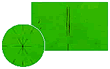





 (Left) Original Image, (Right) Deconvolved Image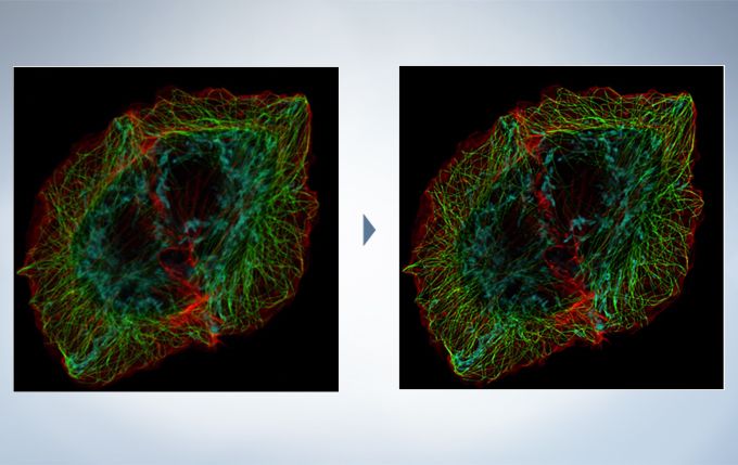
















 실험을 위한 올바른 선택